Currently using a Gen II? Upgrade to the new Gen 3 - our all-new liquid level controller that's even easier for operators to install and adjust in the field.
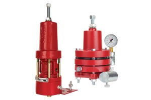
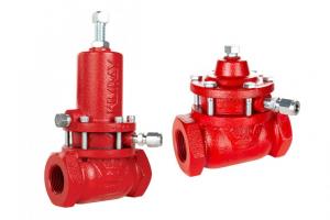
In this video, Will shows you how to repair a Side Mount Gen II Pneumatic Liquid Level Controller.
Skip to the Back Mount Gen II Pneumatic Liquid Level Controller Repair
This repair could also be used if you need to reconfigure your Gen II from right mount to left mount.
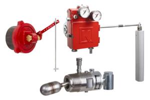
How to Repair the Side Mount Gen II Pneumatic Liquid Level Controller
Here's what you’ll need:
- Needle nose pliers
- Flathead screwdriver
- Adjustable wrench
- 7/64” Allen wrench
- 1/2″ wrench
- 5/16” wrench
- Gen II repair kit (RMD)
- Pick
- Channel locks
If you're planning to modify the spring or displacer, have those parts ready as well.
A feature of the Gen II pilot is that it can be replaced while still connected to the vessel. Choosing to replace the pilot, instead of repairing it, is an accessible option that may be best for your situation. After disconnecting your supply gas, just remove the old pilot and replace it with a newpilot.
If you’re repairing the pilot, or need to work on the tangent arm, start by mounting the unit into a vise.
Open the case and inspect the gasket between cases for rips or tears.
Mark which hole the tangent arm is in and note whether it’s in snap or throttle mode. You could also take a picture for later reference.
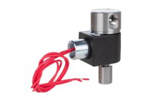
Pilot
Pilot Disassembly
- Remove the two flathead screws from the pilot and remove the pilot from the case.
- Use a pick to remove the three O-rings from the back of the body and discard them.
- Remove the three screws with a 7/64th Allen wrench from the upper cap.
- Hold tension on the cap, and slowly remove them so the top does not pop off.
- Next, remove the diaphragm assembly.
- Turn the assembly over to remove and discard the pilot plug and spring.
- Remove the three screws on the lower cap to remove the actuator assembly. Watch for the spring to fall out. If the diaphragm is stuck, use pliers on the stem of the actuator to pull it out.
- Remove the thumb screw and washer from the switch plate.
- Use a pick to remove the O-rings.
- Lastly, make sure the switch plate and the block are both clear of debris.
With the pilot fully disassembled, we’re ready to open the repair kit.
Pilot Assembly
- Start by putting the new O-rings on the switch plate.
- Attach the switch plate to the block.
- Insert the thumbscrew and tighten.
- Attach the spring to the actuator and insert it into the block. Make sure the lower diaphragm assembly is aligned in the bore before securing the lower cap in place.
- Use Loctite on these three screws.
- Replace the pilot plug, small ball first.
- Apply a small amount of grease and place the spring in the upper cap.
- Apply grease to the assembly where the throttle spring will rest. Then place the throttle spring, small end first, on the upper diaphragm assembly.
- Place the diaphragm assembly into the pilot block, making sure that it sits in the bore and is not hanging over.
- Align the diaphragm and place the top cap over the assembly. Use Loctite on these three screws and confirm that the top cap is sitting evenly to ensure the diaphragm is still in the bore.
- Lastly, replace the three O-rings on the back of the pilot body.
Waggle Arm
Waggle Arm Disassembly
- To begin disassembly on the Waggle Arm, pull out the variable link knob and slide off the tangent arm.
- Using a flat blade screwdriver, pry off the lower end of the variable link knob's yoke. Do not turn the link arm because it is factory set.
- Using needle nose pliers, remove the spring clip from the tangent arm.
- Then remove the retainer snap rings from the pivot post.
- Remove the adjustment lever and leaf spring assembly by sliding the spring assembly back, tilt the adjustment lever back, and slide both to the right. Then slide the adjustment lever off.
If your end goal is to replace this spring, this is as far as you’ll need to go. Swap out for the new spring and begin re-assembly.
If you're performing a full repair or swapping the orientation, follow these steps:
- Continue by removing the pivot plate screws and pull the pivot rod out.
- Remove the coupling on the end of the waggle arm with a ½ inch wrench and a 5/16 or small crescent wrench on the flat.
- Remove the arm post with a ½ inch wrench.
- Unthread the waggle retainer nut and pull the waggle arm out from the mounting.
- Remove the retaining nut from the arm and discard the O-ring and Teflon seal ring.
Waggle Arm Assembly
- Install the retaining nut, Teflon seal, and O-ring on the waggle arm. Be careful to thread or roll these around the threads so they don’t tear.
- Apply Loctite to the housing threads, insert the waggle arm, and tighten with a crescent wrench.
- Then apply Loctite to the arm post and tighten it. Be careful to not over tighten.
- Insert the pivot rod.
- Install the pivot plate using Loctite on the screws. Make sure the pivot rod moves freely and doesn’t bind the assembly
- Install the adjustment and spring assembly by putting the adjustment arm on first, then rotating back to align the spring assembly on the post.
- Use needle nose pliers to install the spring clip.
- Next, install the two snap rings, making sure they snap into the grooves on the posts.
- Install the variable link assembly by first putting the back side of the yoke into the guide pin, then the front side. You may need to use a screwdriver.
- Insert the pull pin onto the end of the tangent arm.
- Install the coupling on the end of the waggle arm with Loctite.
- Replace the O-ring on the filter cap. Clean the filter and replace if necessary.
- Secure the pilot body back into the case, but do not use Loctite on these screws.
- Close the cover and thread on the screw.
- If needed, you can also add an extension rod or convert your displacer from horizontal to vertical orientation.
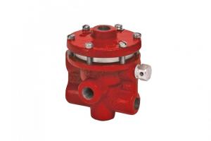
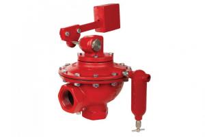
How to Repair the Back Mount Gen II Pneumatic Liquid Level Controller
Here you will find instructions on repairing the Back Mount Gen II Pneumatic Liquid Level Controller.
Here’s what you’ll need:
- Needle nose pliers
- Flathead screwdriver
- 1/8” Allen wrench
- 1/4” Allen wrench
- 7/64” Allen wrench
- A Pick
- And the Gen II repair kit (RMG)
If you’re planning to modify the spring or displacer, have those parts ready as well.
The two most common types of maintenance for the Gen II involve the pilot or the spring. A great feature of the Gen II is that both components can be replaced while the controller is still connected to the vessel.
Before any service, be certain that the valve is fully isolated and that all pressure upstream and downstream has been relieved. Use bypass valves or fully shut off the process.
Replacing the Pilot
You can choose to either repair or replace the pilot, depending on your needs. If you’re replacing the pilot, follow these steps:
- Disconnect your supply gas
- Open the case and inspect the gasket for rips or tears
- Note whether the pilot is in snap or throttle mode and the position of the pull pin.
- Remove the pull pin to relieve tension on the pilot.
- Remove the two flathead screws
- And replace the unit with a new YBU pilot, setting it on either snap or throttle as previously noted
Changing the Spring
The spring balances the weight of the displacer. To change the spring, follow these steps:
- Use a 1/8” Allen wrench to loosen the set screw
- Turn the adjustment knob counterclockwise to unthread it
- Remove the adjustment knob and spring
- Then replace your spring, adjustment knob and set screw
If you’re doing a full product repair, set these parts aside along with the pilot and continue disassembly.
Waggle Arm
Waggle Arm Disassembly
- Mark which hole the tangent arm is in and move the pin to the neutral position to help stabilize the waggle arm assembly.
- Remove the mounting bolts attaching the retainer to the back plate and set the retainer aside
- Remove the pivot rod
- Then pry loose the waggle arm wire, adjustment screw and link
- Remove the back plate from the mounting piece assembly
- Remove the waggle arm from the mounting piece
- Using a pick or similar tool, remove and discard the Teflon seal ring and O-ring
Mounting Piece and Waggle Arm Assembly
- To begin assembly of the mounting piece, install the Teflon backup into the groove
- Next, install the O-ring
- Apply a small amount of grease to the threaded end of the waggle arm and insert it into the mounting piece while slowly rotating clockwise to avoid cutting the O-ring or backup.
- Attach the back plate to the waggle arm housing.
- Insert the adjustment screw through the plate and attach the waggle arm wire.
- Insert the pivot rod into the housing
- Place the retainer over the housing, verifying that the pivot rod sits in the counter bore, then tighten the mounting screws in place
- Install the spring and adjustment knob then tighten the set screw. The adjustment knob and set screw will need to be set specifically for your application.
- Lastly, return the pull pin to its original position.
Before reassembling the displacer on the waggle arm, use Loctite on the coupler.
Pilot Repair
Pilot Disassembly
- Use a pick to remove and discard the three O-rings from the back of the body
- Remove the three screws with a 7/64th Allen wrench from the snap adjustment housing.
- Hold tension on the cap, and slowly remove them so the top does not pop off.
- Discard the spring and spring plate.
- Next, remove and discard the diaphragm assembly. If the diaphragm is stuck, use pliers on the stem of the actuator to pull it out.
- Turn the assembly over and discard the pilot plug and throttle spring.
- Remove the three screws on the lower cap to remove the actuator assembly. Discard the assembly, lower cap and spring.
- Remove the thumb screw, washer and switch plate from the block.
- Then use a pick to remove the O-rings from the back of the switch plate.
- Lastly, make sure the switch plate and the block are both clear of debris.
Now that everything is fully disassembled, we’re ready to open the repair kit.
Pilot Assembly
- Start by putting the new O-rings on the switch plate.
- Attach the switch plate to the block using the washer and thumbscrew.
- Attach the spring to the actuator and insert it into the block. Make sure the lower diaphragm assembly is aligned in the bore before securing the lower cap in place.
- Attach the lower cap using Loctite on the three screws.
- Replace the pilot plug, small ball first.
- Apply a small amount of grease and place the spring and spring plate in the upper cap.
- Apply grease to the assembly where the throttle spring will rest. Then place the throttle spring, small end first, on the upper diaphragm assembly.
- Apply Loctite to the three screws to have them ready.
- Place the diaphragm assembly into the pilot block, making sure that it sits in the bore and is not hanging over.
- Align the diaphragm and place the top cap over the assembly. Confirm that the top cap is sitting evenly to ensure the diaphragm is still in the bore before tightening.
- Lastly, replace the three O-rings on the back of the pilot body.
If you have any questions about this repair, contact your local Kimray store or authorized distributor.