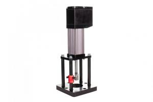
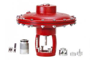
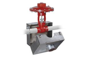

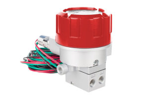
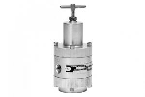
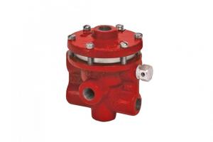
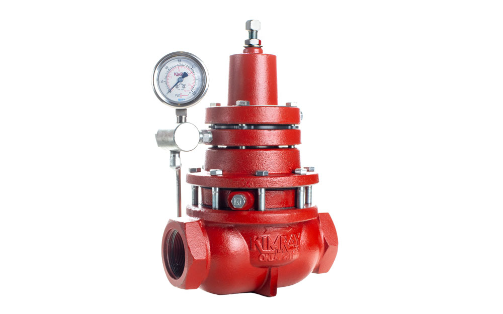
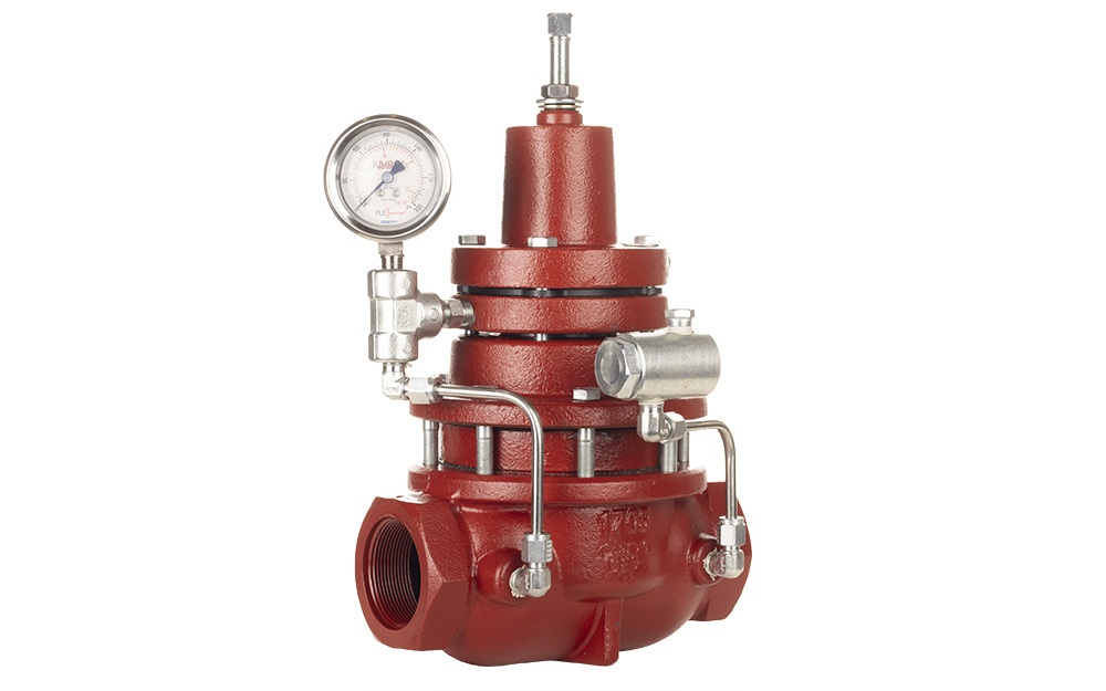
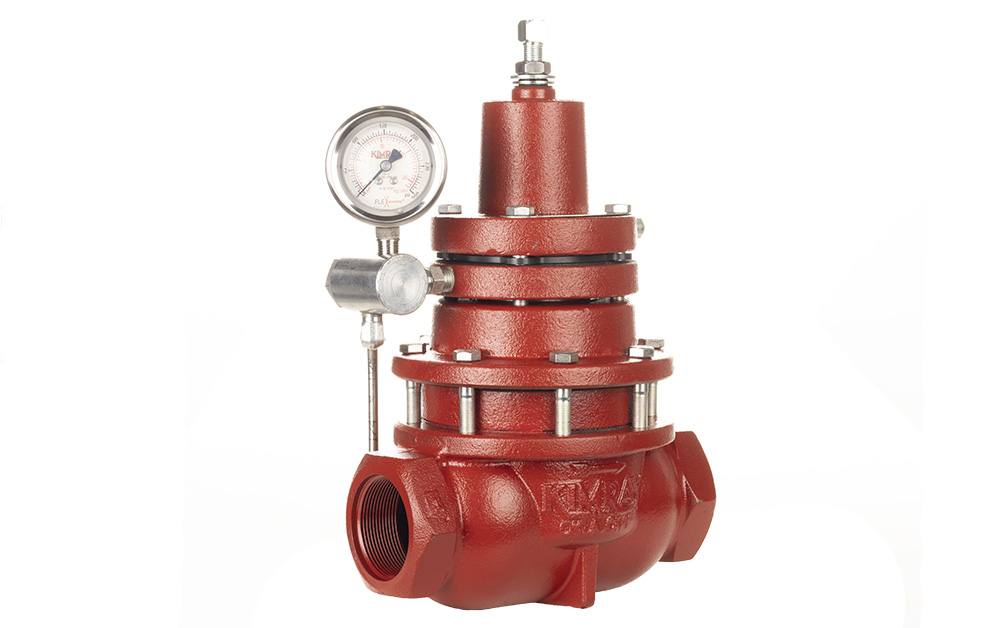
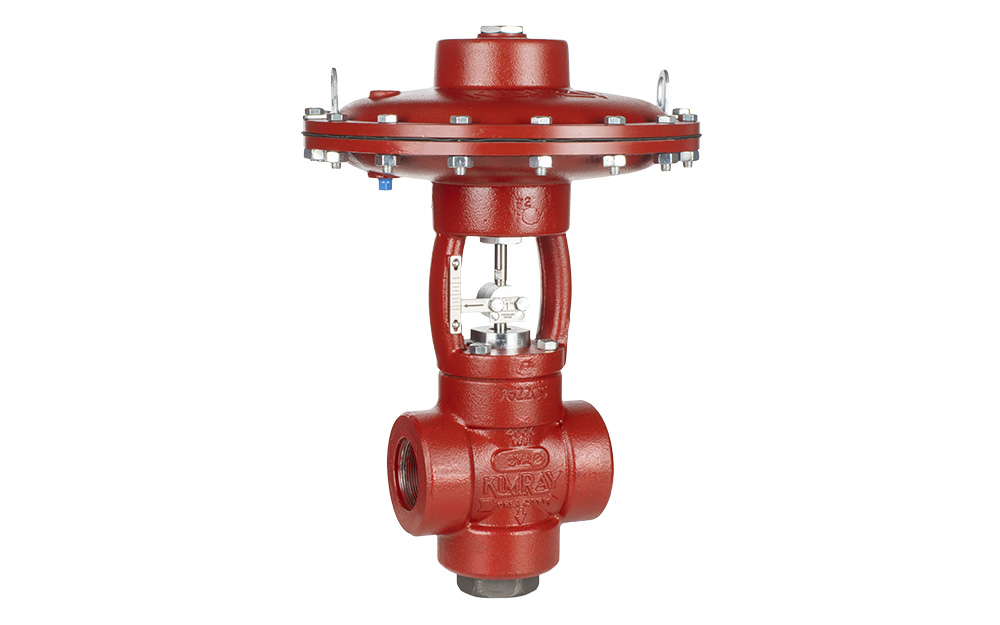
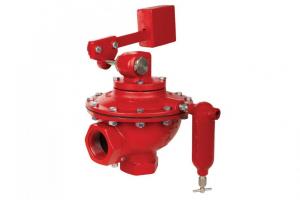
This is a walkthrough of how to repair a Pneumatic Diaphragm Balanced Liquid Dump Valve.
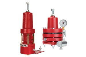
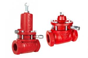
Pneumatic liquid dump valves are available in either pressure-opening or pressure-closing configurations. We will be using the pressure-opening model for this repair.
How Often Should I Perform Maintenance on a liquid Dump Valve?
Though the body of a liquid dump valve will last for many years, the seals should be replaced at least once a year.
We also recommend inspecting the valve seat every 6 months under normal service and conditions. Under severe service applications, inspection should be done regularly until a predictable pattern can be established for maintenance.
Parts Needed
For this job, you will need the following tools, equipment, and chemicals:
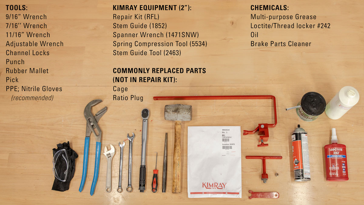
Tools
- 9/16” Wrench
- 7/16’’ Wrench
- 11/16” Wrench
- Adjustable Wrench
- Channel locks
- Punch
- Rubber mallet
- Pick
- PPE; Nitrile Gloves (recommended)
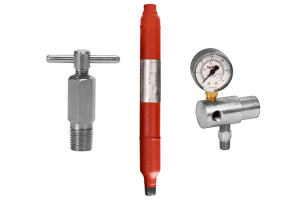
Kimray Equipment (2”)
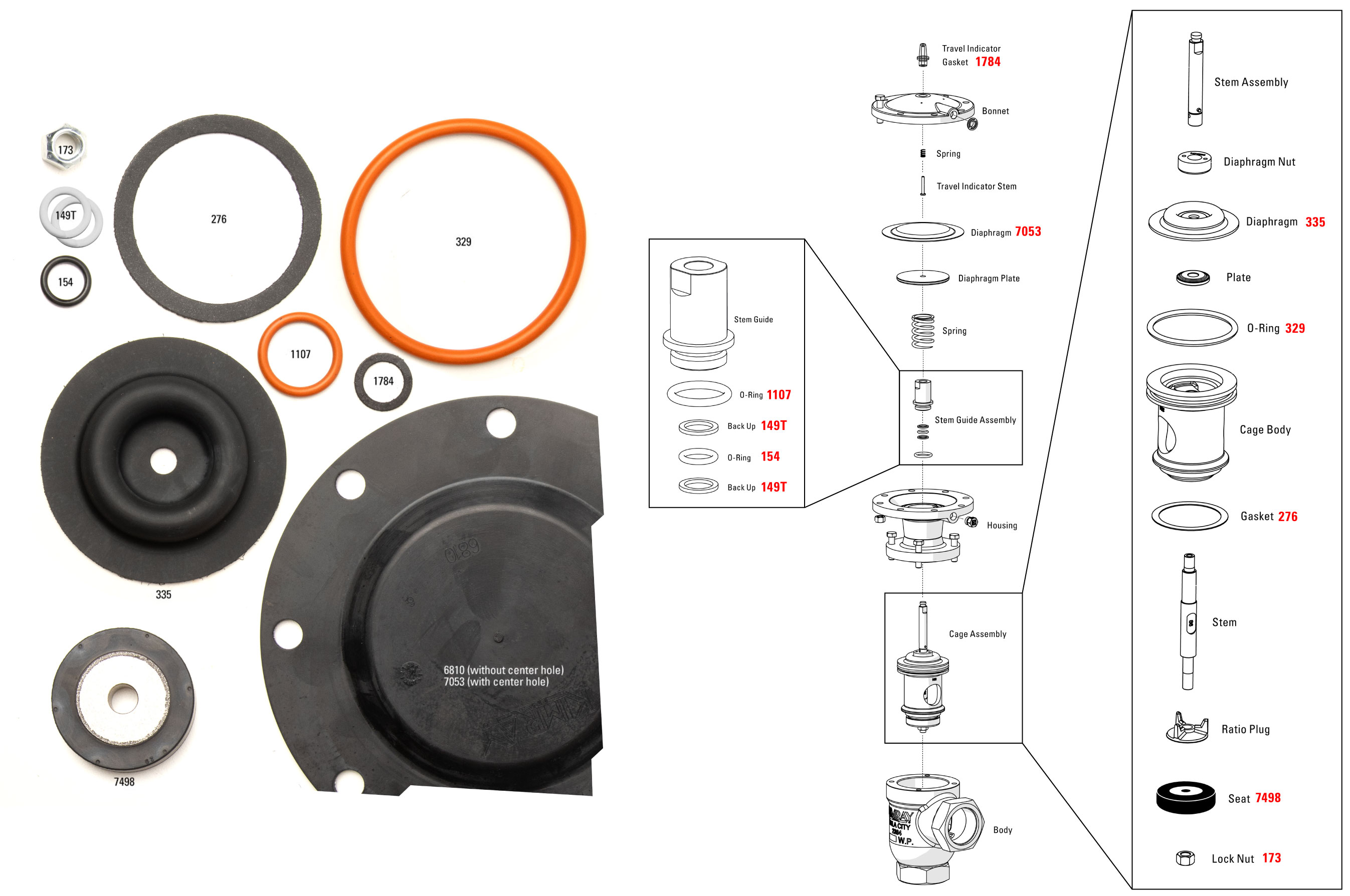
- Repair Kit (RFL)
- Stem Guide (1852)
- Spanner Wrench (1471SNW)
- Spring Compression Tool (5534)
- Stem Guide Tool (2463)
- Commonly Replaced Parts (not in repair kit):
- Cage
- Ratio Plug
- Commonly Replaced Parts (not in repair kit):
Chemicals
- Multi-purpose Grease
- Loctite/Thread locker #242
- Oil
- Brake Parts Cleaner
Safety
Before any service, be certain that the valve is fully isolated and that all pressure upstream and downstream has been relieved. Use bypass valves or fully shut off the process. Be sure that any operating or instrument gas lines have been disconnected.
How to Disassemble the Pneumatic Diaphragm Balanced Liquid Dump Valve
- Remove the breather plug from the housing with a 9/16” wrench.
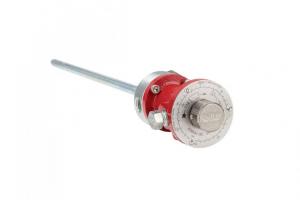
- Remove the travel indicator housing with an adjustable wrench. Be careful because it will pop out.
- Remove the spring and the travel indicator stem and set them aside.
- The gasket will come off with the housing or may be stuck to the bonnet. Remove and discard.
- Use a 9/16 and 11/16” wrench to remove the nuts and bolts from the bonnet. You may need a flathead screwdriver or a similar tool to separate the bonnet from the housing.
- Remove and discard the diaphragm.
- The spring behind the diaphragm plate is spring loaded so be careful when disassembling. Loosen the diaphragm plate with Channellocks. Then apply downward pressure while carefully unthreading by hand to remove fully.
- Remove the spring.
- Use a 9/16” wrench to remove the bolts from the lower housing.
- Carefully pour out and discard the oil from the housing.
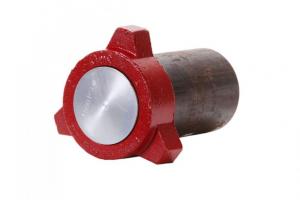
“Cage Assembly” Disassembly
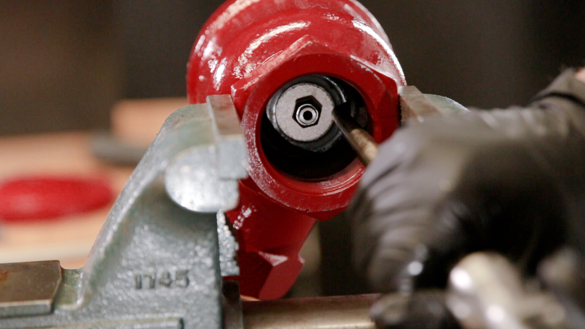
- Secure the body in the vise at a 90° angle.
- Use a large punch to tap out the cage assembly through the top of the body. Be careful not to strike the stem and to only use the punch on the seat. Remove it in a controlled manner and do not let it fall out, which could cause damage or injury.
- Remove the body from the vise.
- Secure the cage assembly in the vise by the lock nut.
- Use a spanner wrench or Kimray Diaphragm Nut Removal Tool to hold the diaphragm nut still while you unthread the stem assembly with an adjustable wrench.
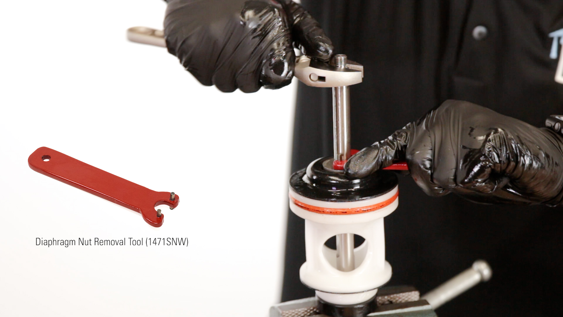
- Put a 7/16” wrench on the flats of the stem and remove the diaphragm nut with the Kimray tool.
- Remove and discard the diaphragm.
- Then remove the plate and set it aside.
- Use a pick to remove and discard the large O-ring from around the cage.
- Then remove the cage from the stem.
- Use a 7/16” wrench on the flats to remove the stem.
- Remove and discard the gasket from the bottom of the cage. This could also be stuck inside the valve. Be sure to remove any fragments of the old gasket from both surfaces.
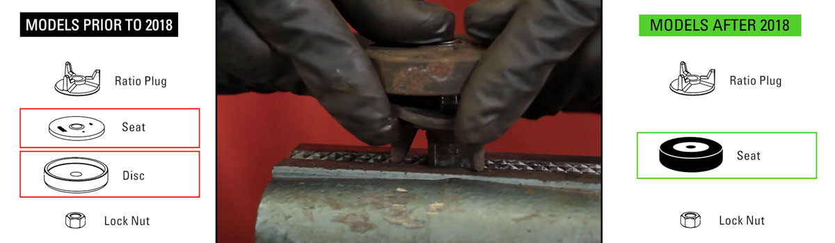
- Remove and discard the seat but keep the ratio plug. The separate disc and seat found on models prior to 2018 has been replaced by a reversible seat. If only one side is worn, it can be flipped 180° to be used again or replaced from the repair kit.
- Remove the nut from the vise and discard.
“Stem Guide Assembly” Disassembly
- Put the housing in a vise and use the Kimray Stem Guide tool to remove the stem guide assembly.
- Remove and discard the O-ring around the threads of the stem guide.
- Then, remove and discard the backup, O-ring and second backup.
- At this point, your valve is disassembled and you’re ready to inspect the parts.
how to inspect and clean the Pneumatic Diaphragm Balanced Liquid Dump Valve
- Clean around the O-ring groove on the stem guide. Any loose particles left in the groove could cause leakage. If the groove surface shows light scratches, it may need to be replaced.
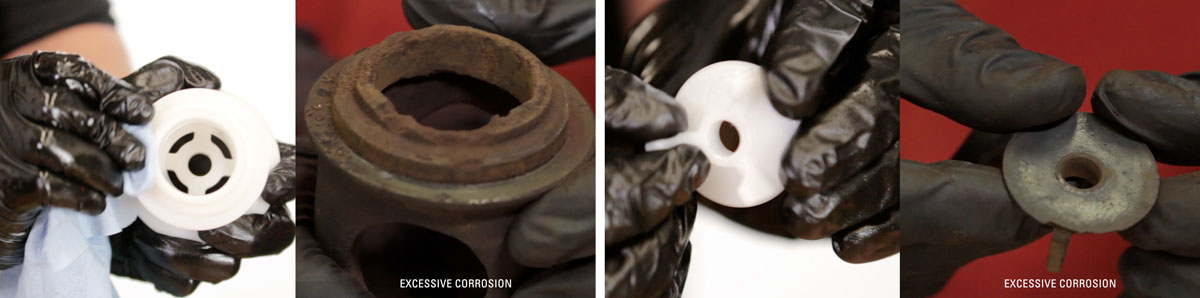
- Inspect the bottom surface of the cage. If there is excessive corrosion or erosion, or any damage that could create a leak path between the cage and seat, discard and replace.
- Also check for fragments of gasket material, which can cause misalignment of the body surface. Use a flat file to clean the surface, but replace the cage if there are deep nicks that cannot be removed or if the cage body shows signs of wear.
- Inspect the ratio plug. If there is an excessive amount of corrosion or erosion, it will need to be replaced.
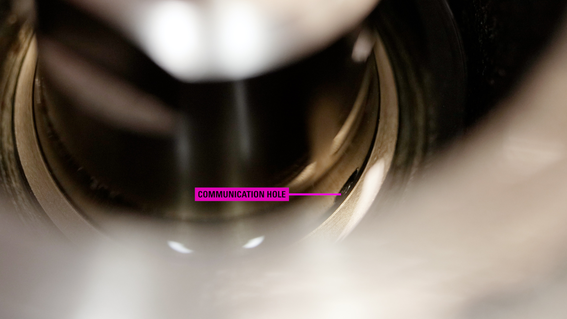
- Clear the stem guide communication hole of any debris.
- Check the diaphragm nut to make sure the threads are intact, and that the communication hole is clear of debris.
- On the valve body, inspect the inlet and outlet threads to make sure they are intact.
- Inspect the seat area where the gasket will sit and check for any severe washouts inside the valve.
- Clean the interior and exterior to make sure it’s free of all solvents, debris, and fluids that may damage elastomers and affect O-ring and gasket seals.
- Use a parts washer or a wire brush, degreaser, and the appropriate PPE to get them as clean as possible.
How to Assemble the Pneumatic Diaphragm Balanced Liquid Dump Valve
“Stem Guide” Assembly
- Place the housing in the vice.
- Apply all-purpose grease to the threads of the stem guide.
- Place the (1107) O-ring onto the outer groove of the stem guide and apply grease.
- Put in the first (149T) spiral back up, followed by the (154) O-ring and the second (149T) back up.
- Add grease to the inside.
- Tighten the stem guide into the housing.
“Cage Assembly” Assembly
- Place the new (329) O-ring onto the cage.
- Apply grease to the O-ring.
- Then apply grease to the bottom of the cage where the gasket will set.
- Put on the (276) gasket and apply grease. Then set the cage aside.
- While holding the stem, slide on the ratio plug, followed by the (7498) seat. If you’re using a reversed seat, put the worn side facing away from the ratio plug.
- Hand start the new (173) lock nut onto the valve stem, making sure the flat end of the nut is facing the seat.
- Flip the stem over and tighten the nut into the vise.
- Use a 7/16”wrench on the flat area of the stem to fully tighten.
- Slide the cage over the stem.
- Followed by the plate.
- Place the (335) diaphragm over the plate with the raised side facing up.
- Hand start the diaphragm nut onto the threads.
- Apply Loctite to the threads. Use a spanner wrench or Kimray Diaphragm Nut Removal Tool to fully tighten the diaphragm nut.
- Then thread the stem assembly into the lower stem using an adjustable wrench.
- Now secure the valve body in the vise and insert the cage assembly with the hole facing the same direction as the valve connection.
- Tap on top of the cage with a rubber mallet while applying pressure to the opposite side until the cage seats fully. The diaphragm edge must be near flush with the body.
- Place a Kimray Stem Guide on top of the stem.
Body, Cage, & Housing Assembly
- Seat the housing on the valve body. The breather plug should be parallel to the valve inlet.
- Remove the stem guide.
- Tighten the bolts in a crisscross pattern to avoid misalignment. For 2”, 3” and 4” valves, tighten bolts between 25-30 ft/lbs torque.
- Apply 5/8” to ¾" of oil into the housing—enough to cover the communication hole.
- Thread on the diaphragm plate. Then use two flathead screwdrivers to make sure the stem is all the way up.
- Now remove the plate and install the spring into the housing.
Diaphragm Plate Assembly
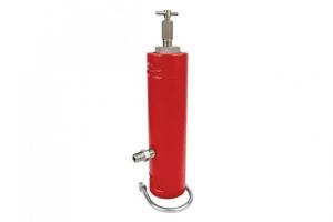
- To install the diaphragm plate, you’ll need to use the Kimray Spring Compression tool.
- Attach the tool to the housing and tighten it securely. Carefully compress the spring by pulling down on the lever. Then thread on the diaphragm plate by hand—about three full rotations.
- Relax the spring pressure while assuring the plate remains in place. It’s important to make sure that the spring stays under the compressor tool.
- Carefully remove the spring compression tool. You can use a wrench to loosen the wing nut on the tool.
- Before fully tightening, apply thread locker (Loctite) to the exposed threads.
- Now tighten by hand until snug, and use channel locks to tighten fully. When it’s tight, the top of the stem should be flush or slightly above the plate.
Diaphragm, Bonnet, Breather Plug, Travel Indicator Assembly
- Place the (6810) diaphragm over the diaphragm plate, bevel side up, and center with the bolt holes.
- Place the bonnet on the housing and align the supply inlet with the housing breather hole.
- Place the bolts in the bonnet and tighten the nuts in a crisscross pattern between 25-30 ft/lbs. torque. If your valve has hoist rings, attach them across from each other.
- Place the spring on the indicator stem. Then place this into the bonnet.
- Place the (1784) gasket on the travel indicator housing.
- Insert the travel indicator housing into the bonnet and tighten with an adjustable wrench.
- Apply thread locker to the breather plug threads and install it into the upper housing.
- Tighten until seated and the hole is facing down.
For any other questions regarding this repair or any other Kimray product, contact your local Kimray store or authorized distributor.