

A gas dehydration system is used by oil and gas producers to dehydrate natural gas into a state where it can be sold downstream. In this video, we follow the pipes around a gas dehydration system and explains what each piece of equipment is doing to process the gas.
Gas Dehydration System Inlet
The inlet to the typical gathering station is for several different wells. After going through the main line, slug catcher and manifold, the gas is run through compressors.
Once the gas has been compressed, it flows from the compressor discharge into to the contactor tower.
Three-Valve Manifold
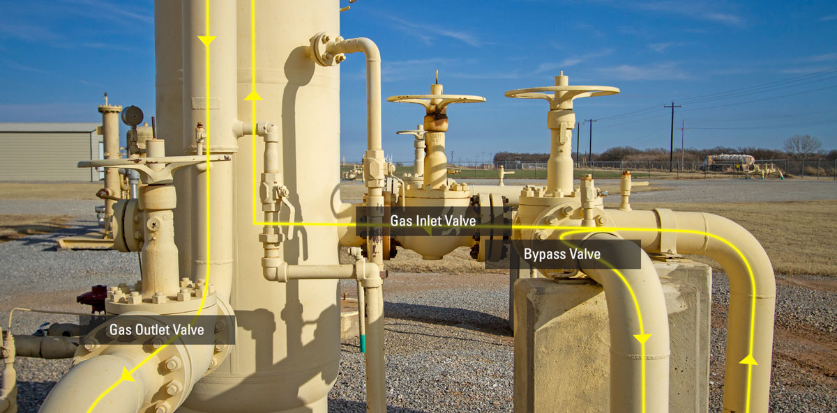
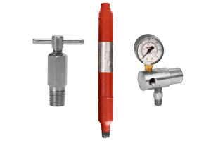
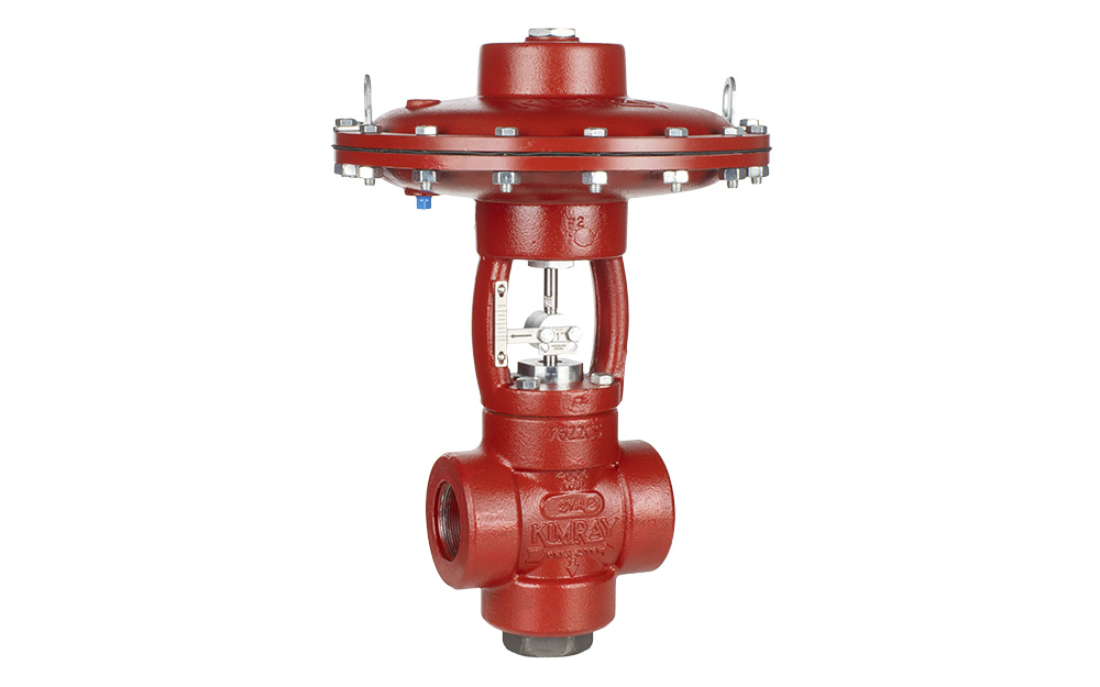
Located at the base of the contactor tower, there is a three-valve manifold which includes the gas inlet valve, bypass valve and gas outlet valve.
On startup of the gas dehydration system, all three valves are opened. This allows gas to bypass the tower but also allows gas from the pipeline to pressurize the tower.
After the entire startup procedure has been completed, the bypass valve will be slowly closed, forcing all of the gas from the compressors into the bottom of the contactor tower.
Contactor Tower
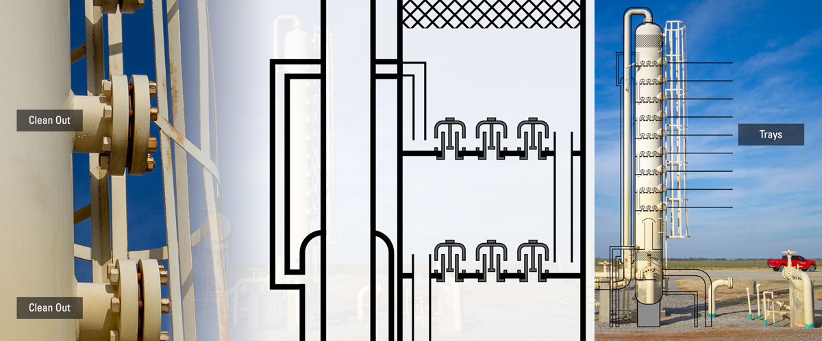
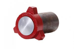
The glycol contactor tower is sometimes called an absorber tower. Inside the tower are trays, approximately 18 inches apart, indicated on the outside by clean outs. Those enclosures can be removed to clean debris off the trays.
Temperature and Pressure Gauges
Three things are required to calculate the size of a glycol pump: temperature, pressure, and flow rate. The gas temperature needed for this calculation is located at the contactor tower.
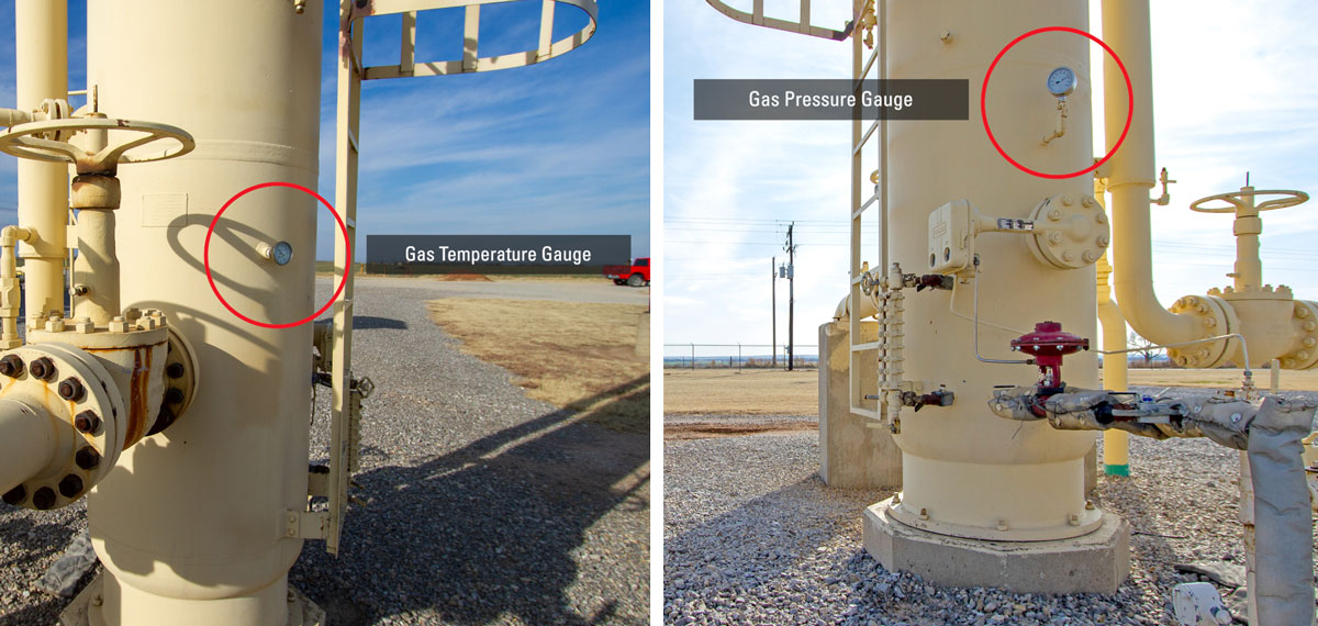
On the tower in the video, the gas temperature is 82 degrees. The pressure gauge shows that it’s operating at about 760 pounds.
The producer can supply the flow rate or it can come from a meter at the sales point.
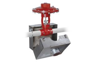
Liquid Level Controller & Dump Valve
At the base of the contactor tower is a liquid level controller, dump valve and sight glass. These components help eliminate any free water, condensate or contaminates from coming into contact with the triethylene glycol, or TEG, in the tower.
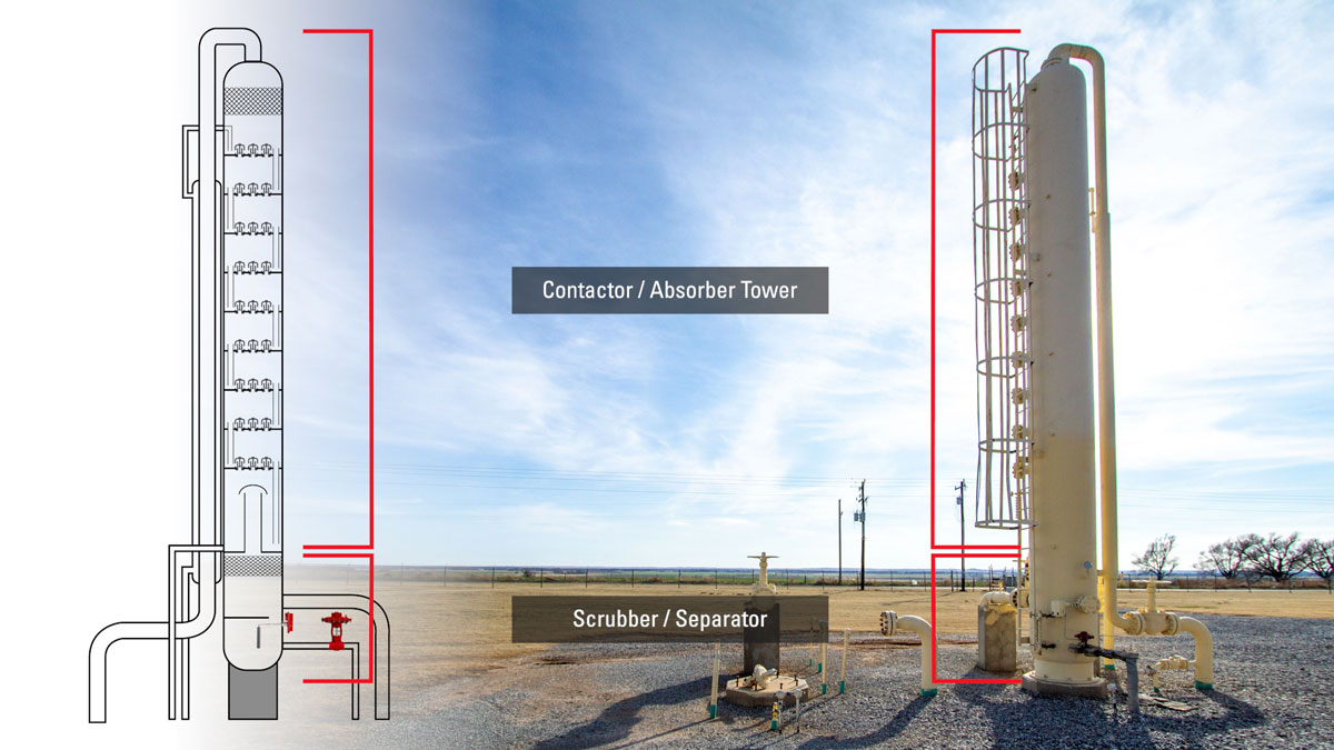
This tower has a scrubber built in, but some location may have a standalone separator before it reaches the contactor tower.
Gas Outlet to the Meter Run
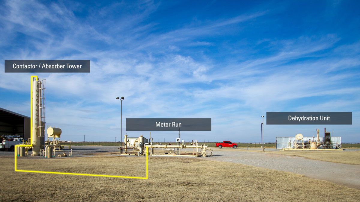
Once the gas has been dehydrated within the tower, the gas flows to the meter run to be measured and sent off site for further processing.
Gas Dehydration System Reboiler
Before starting a dehydration unit, we would look at the level of glycol shown in the sight glass on the reboiler. After we’ve made sure that the reboiler is full of glycol, then we would light the burner.
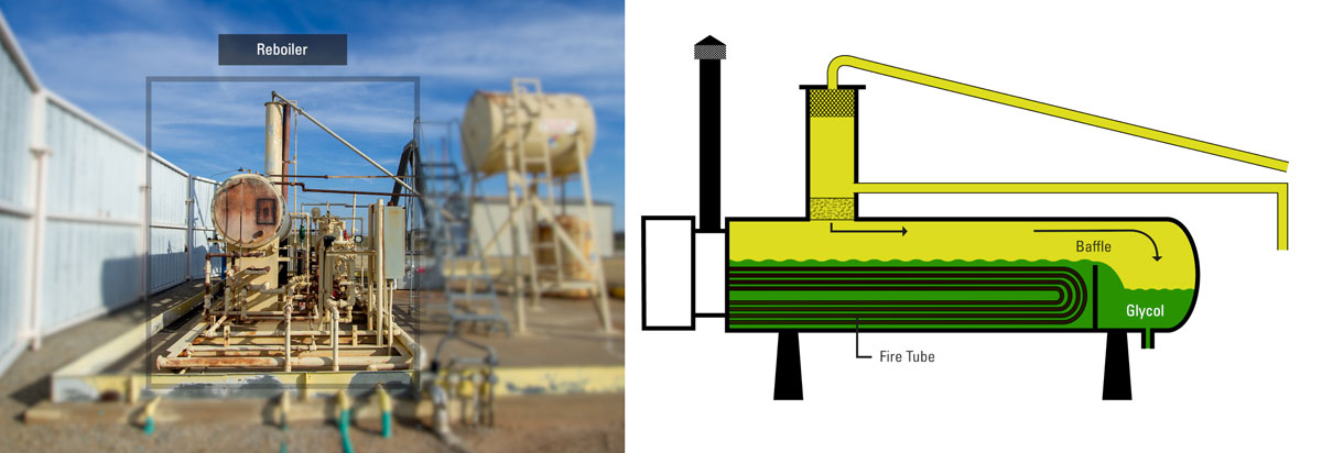
The reboiler in the video looks like a single vessel, but is actually two pieces–the reboiler and the surge tank. There is a baffle that will ensure the glycol level will cover the fire tube. The regenerated glycol then flows over that baffle and into the surge tank.
There is the high temperature shutdown thermostat and a thermostat controlling the main burner both set to the appropriate settings.
Inside the burner assembly, or flame arrestor, is a standing pilot and a main burner. After the burner is lit, the TEG in the reboiler will begin to warm up to 375 degrees before we start circulating the glycol.
The gas from the contactor tower also comes into the boiler skid to provide instrument gas for the thermostat and the control valves as well as provides the drive to make the pump operate and allow the triethylene glycol to circulate.
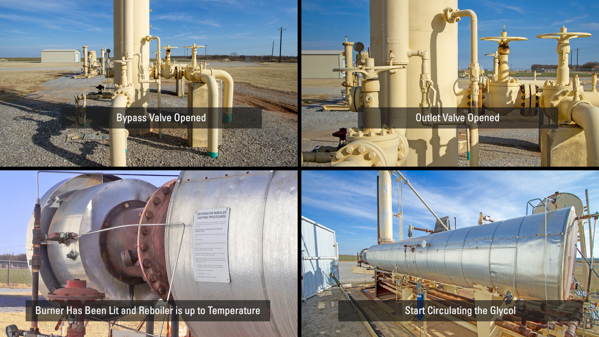
To recap this process:
- the bypass valve is open to allow gas to go around the contactor tower
- the outlet of the tower is open, so there’s equalized pressure throughout the tower
- the burner has been lit and the reboiler is up to temperature
- so, now it’s time to start circulating the glycol
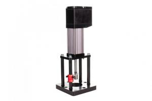
Surge Tank
On some gas dehydration sites, the surge tank is part of the reboiler.
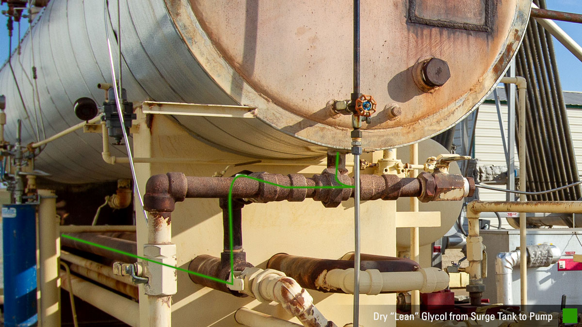
TEG comes out of the surge tank at 375 degrees and as seen here, has burned the paint off the piping. Lean or dry glycol exits the surge tank and moves through the considerable amount of piping related to the heat exchangers.
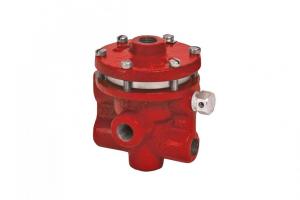
Y Strainer
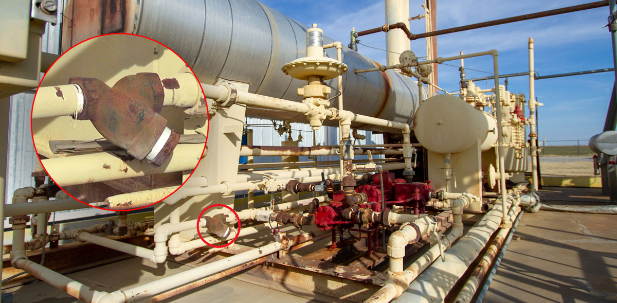
The Y strainer is a simple but important device that blocks rust or particles that may have come from the re-boiler before going into the pump.
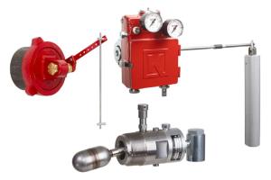
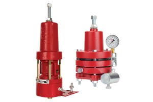
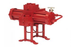
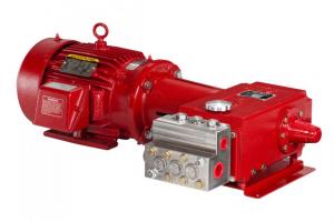
Glycol Pump for Gas Dehydration
The lean glycol flows to the suction of the pump through the Y strainer. The lean glycol travels through the internal workings of the pump, ending up at the discharge block of the pump.
This is the proper sound of a 450-energy exchange glycol pump stroking. It sounds cushioned–there’s no metal-to-metal sound.
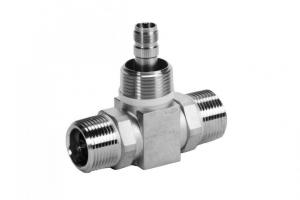
Check Valve
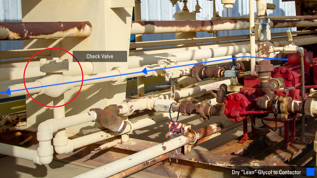
After the lean glycol has moved through the pump, it passes through a check valve which is installed to help reduce wear and tear on the pump. A check valve can stick and be restricted by rust so it’s a good place to troubleshoot from time to time.
Gas Dehydration: Lean to Rich Glycol
Lean glycol continues down a pipe underground to the contactor tower. The natural cooling the earth provides acts as a heat exchange and cools the glycol down more before it enters the tower.
The lean glycol inlet to the tower goes up a gas-to-glycol heat exchanger. It then enters the top of the tower and drops the glycol down through the series of trays.
As gas is coming up through the bottom of the tower and glycol is flowing down from the top of the tower.
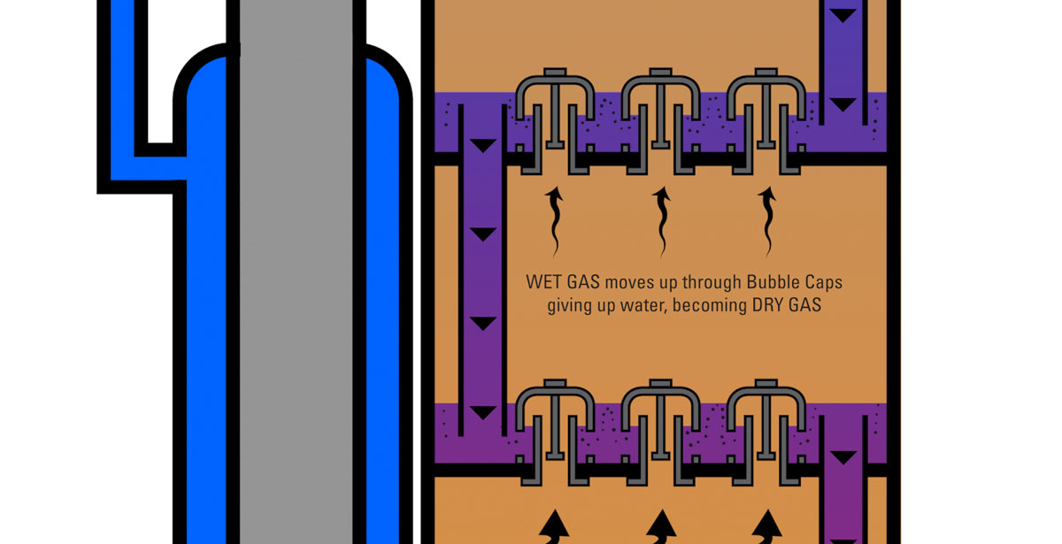
The gas flows up through bubble caps, which forces it to contact the downward flowing glycol. The gas gives up water and becomes dryer as it passes up through each succeeding tray to meet pipeline criteria as it leaves the top of the tower.
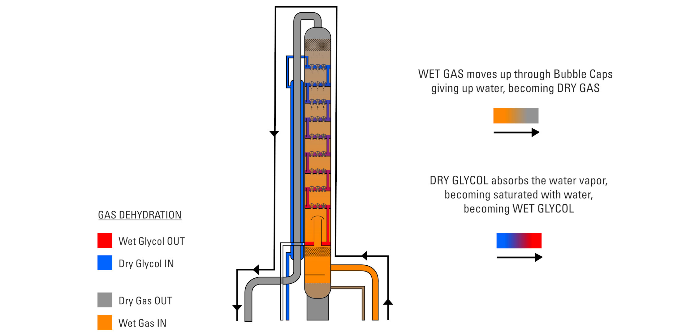
Water vapor in the gas is absorbed by the TEG and the lean glycol then becomes saturated with water, becoming “rich” or wet glycol where it leaves the bottom of the tower and back to the reboiler to be regenerated.
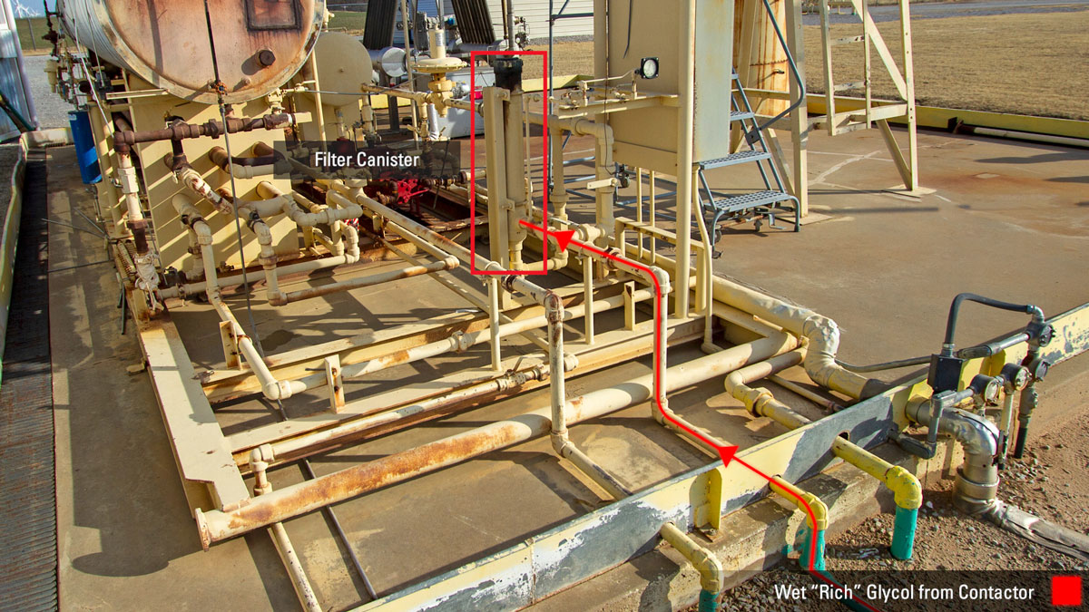
After the wet glycol leaves the tower, it passes through a filter canister before entering the glycol pump. This filter is critical to reducing wear to the glycol pump and avoid plugging of the heat exchanger and must be regularly cleaned or replaced.
As it enters the pump, this rich glycol travels through the internal workings and helps move the pistons back and forth.
The rich glycol comes out of the pump and at the location in the video experiencing a pressure drop from 750-pound operating pressure to atmosphere. It travels through pipe and starts to be used in the glycol-to-glycol heat exchange system.
Glycol-to-Glycol Heat Exchange System
A glycol-to-glycol heat exchange system works because the pressure drop creates a temperature drop. That temperature drop then acts as a cooling agent.
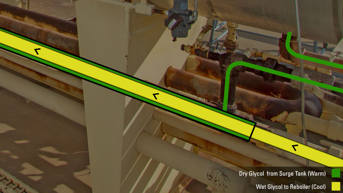
As cool glycol is going through the pipe, the warm, dry glycol is coming out of the surge tank on the outside of the pipe. The wet and the dry never come into direct contact with each other. The cooling effect caused by the movement of the two temperatures of glycol, cool the glycol down as it goes through the system.
The rich comes out the other end of the exchanger and into the flash separator.
Flash Separator
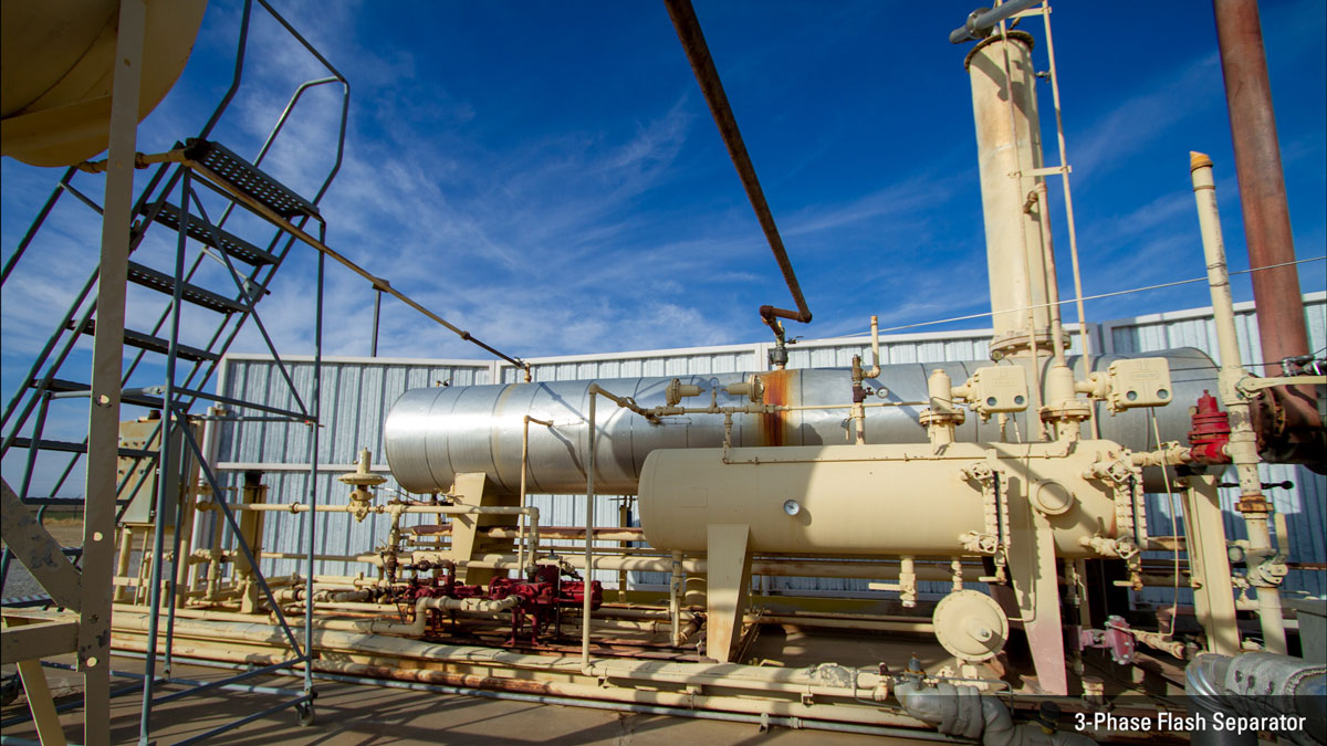
The three-phase flash separator separates the rich glycol from contaminants, lubrication oil, free water, and condensate. The contaminated liquids exit and are moved to a storage tank.
Still Column
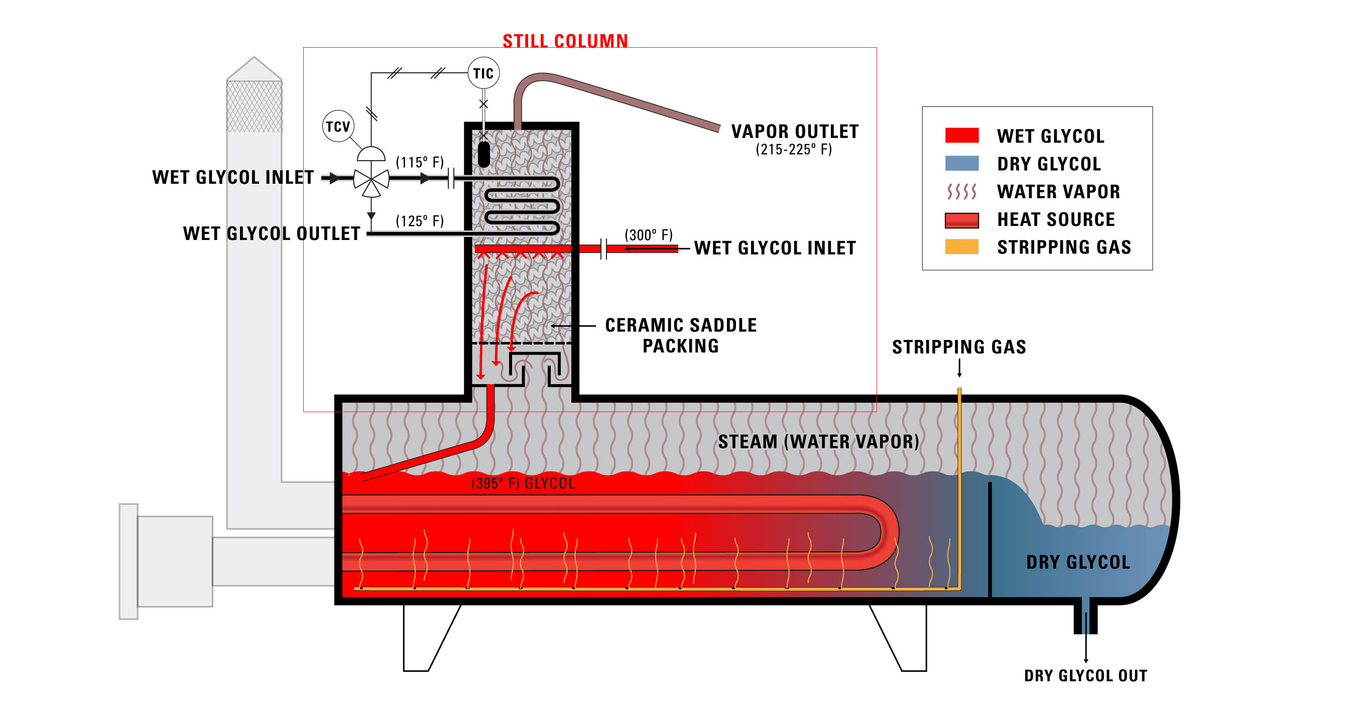
The glycol comes out of this system and into the inlet of the still column. The still column is a packed column which allows the rich glycol to drop down through it.
That glycol, rich with water, hits the 375-degree glycol. Water, which boils at 212 degrees F, flashes off as steam. The steam goes back through the still column, but the glycol is trapped and dropped back into the reboiler.
The glycol then goes through the reboiler and starts its journey over again, multiple times a day. Typically, the glycol will last 18-24 months before it needs to be changed.
BTEX
A very important safety feature of a gas dehydration system is the BTEX.
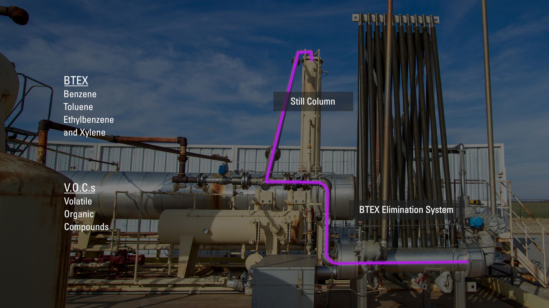
The steam from the still column enters the BTEX (benzene, toluene, ethylbenzene and xylene) elimination system used to capture and recycle BTEX and VOCs (volatile organic compounds).
The contaminated steam is condensed back to liquid and collected and transferred to storage, while the residual VOC vapors are sent to the burner to be incinerated.
To speak with an expert about your gas dehydration system, contact your local Kimray store or authorized distributor.