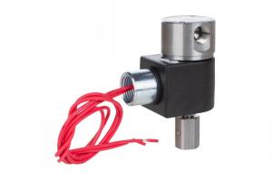
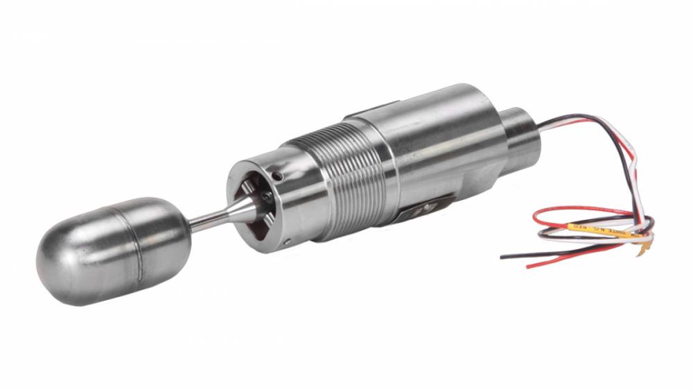
The Kimray Horizontal Electric Liquid Level Switch was originally developed to operate solenoids, relays, and small motors. These devices typically require several watts of power, and fit well in the range of 3W to 100W for the standard horizontal level switch.
However, with the industry moving to automation and process monitoring, there is a need to operate in the microwatt range of power typically provided by PLCs, RTUs, and other distributed control systems.
The low power Kimray Electric Liquid Level Switch covers the range of 0W to 25W of power. This fits in nicely with the demands of today’s automation equipment.
If you use a standard switch in a low power application, you can experience false-open readings after some time. This is caused by an aged buildup on the contacts due to the lack of necessary current to keep the contact surfaces clean. Typically, the contacts can be refreshed by applying a heavier switching load to the contacts even for a short amount of time. The Kimray Electric Liquid Level Switch employs rhodium contacts that prevent potential oxidation issues.
Electrical Ratings
| Standard | 0.83 A @ 120 VAC 2A @ 50 VDC 3A Maximum PWR: 3W MIN, 100W Max |
| Low Power | 0.2A @ 120 VAC 1A @ 25 VDC 1A Maximum PWR: 25W Max |
Problems?
Are the Electronic Level Switches eating your lunch? There are any number of issues that could cause you some headaches with these controllers. This is especially true if you are not all that familiar with them. You may be testing them incorrectly or operating them outside of the electronic parameters they were designed for. Before you become frustrated with these controllers we should take a look at a few things.
Here is some basic information and testing procedures for the Electric Liquid Level Switch:
Horizontal Switch Load Ratings
The Kimray CEB1/CEB2/CEC1/CEC2 level switches are rated at 3W minimum load, 100W Maximum load. They employ a mechanical reed switch which uses Tungsten contacts.
Using The Level Switch Below The Minimum Rating
If the level switch has been in operation for some period of time with a switching load of less than 3W, there is a possibility that the tungsten contacts in the internal reeds switch have become oxidized and will increase in resistance. This would be observed when measuring an increased resistance in closed contacts. Typically, a user can expect the closed contact resistance to be a few Ohms or less.
Identifying Potential Oxidation Issues
If the contact resistance is much higher than a few Ohms, or the resistance of closed contacts seem to be reading erratically, it is very possible that the contacts have become oxidized. This effect can usually be repaired by applying a heavier switching load to the contacts. There are a number of ways this could be done. It all comes down to allowing electric current to flow through the contacts.
Bench Testing the Horizontal Level Switch
Here’s how to bench test a level switch to check for contact oxidation.
- Disconnect the level switch from the monitoring circuit.
- Measure and record the open and closed resistance for each of the contact pairs:
- normally open (NO) and common (COM)
- normally closed (NC) and common (COM)
- Apply a switching load of greater than 3W, but less than 100W to the normally open pair.
- Actuate the manual override (if equipped) and verify that the load switches on and off appropriately. If a manual override is not available; then raising the level in the tank, or manually operating the float will be needed.
- Move the switching load to the normally closed pair.
- Actuate the level switch and verify that the load turns off and on appropriately.
- Disconnect the switching load from the level switch and measure the open/closed resistance for each of the pairs again.
By operating a heavier load with the switch the contacts will have conducted a higher current that can burn through any oxidation and provide clean contacts once again. However, this will not prevent reoccurrence if the level switch is controlling a very light load (<3W).
Preventing Problems
If the switch is connected to a minimum load of 3W, oxidation should not become a problem. If the switch is connected to a much lighter load, the above bench testing method may temporarily clean the contacts. But this will not prevent the oxidation from a re-forming over time.
A Case Example
One occasion of this type of failure came from a customer report of a level switch falsely indicating liquid level on a known empty vessel. The level switch was then removed from the vessel and returned to Kimray. Upon receiving the level switch, the switch contacts were tested with an Ohmmeter and found to be working correctly—the customer complaint could not be verified.
Upon further investigation, the application was discovered to be detecting the level switch using a micro controller with very low current levels (micro-amp range).
At these low currents, it only takes a thin oxidation layer to dramatically increase the resistance of the contacts. This causes a false reading of the level position. The auto-ranging Ohmmeter can supply a varying amount of current. In this particular case, simply measuring the resistance of the contacts apparently corrected the minor amount of oxidation present, thereby “repairing” the level switch.
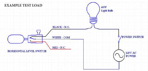
This is an example of a simple circuit for testing the level switch using an ordinary household 60W light bulb.
By closing the power switch and manually moving the float (or manual override), the light will turn on and off as the float makes and breaks contact of the reed switch.
In the above circuit, the level switch is controlling a 60W load.
The maximum voltage the switch contacts experience is 120VAC. The maximum current through the contacts is approximately 500mA AC current.
An Application Example 1: Driving a Relay
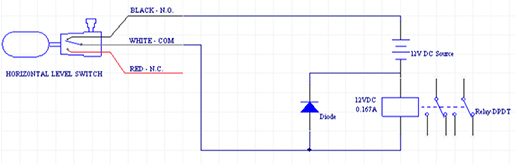
In this example application, the Horizontal Level Switch is controlling a 12V DC DPDT relay. The relay coil is rated at 12VDC, 0.167A (2.0W. That is below the minimum switch rating for the horizontal Level Switch. This application might experience failure over time caused by oxidation of the contacts.
An easy solution for this application is to add a parallel resistance to the relay – increasing the overall switching power of the circuit.
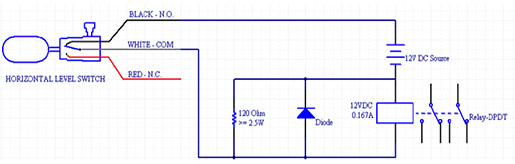
In this Circuit, the relay is still only consuming 2W of power. However, the parallel resistor is drawing an additional 100mA (12V / 120 Ohms = 0.10 A) and consuming an additional 1.2 W of power [(12V ^2) / 120 Ohms = 1.2W]. It is good practice to use a safety factor of at least 2.0 when selecting wattage of resistors.
Since the resistor normally consumes 1.2 W of power, it should be selected with a power rating of greater than 2.4W. Total power consumption of the switched load is now 3.2W.
Application Example 2: Driving A High Impedance Input
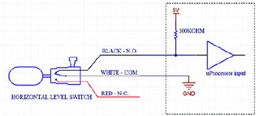
In this circuit, a uProcessor reads the horizontal switch. A 100KOhm resistor pulls high the input buffer. The input buffer itself has a very high impedance input. When the switch is in the closed position, the uProcessor should read a high input near 5V. When the switch is closed, the user would expect the input to be very low – close to 0V.
However, the closed contacts of the switch only see (5V / 100K Ohm =) 50uA of current. The resistor only consumes [(5V ^ 2) / 100K Ohm=] 0.25mW of power. The tungsten contacts in the level switch can easily begin to build oxidation under these conditions causing the switch contact resistance to dramatically increase. If there is sufficient current available from the 5V source, you could fix this circuit by replacing the 100K pull-up with a low value power resistor…
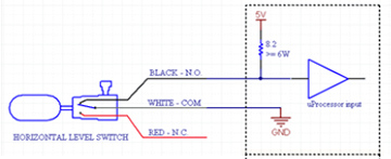
In this circuit, the uProcessor still reads 5V for open, 0V for closed, but the switch is now driving a [(SV ^ 2) / 8.2Ohms = ] 3.0W load. Current through the resistor is now 0.61A.
If a higher voltage is available, you can reconfigure the circuit as follows:
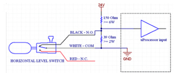
The above circuit reads 4.95V for closed contacts and the switch is driving a 3.8W load. For open contacts, the uProcessor reads near 0.0V and the resistor divider power consumption is 3.0W.