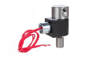
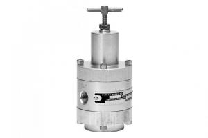
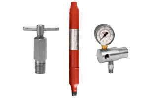
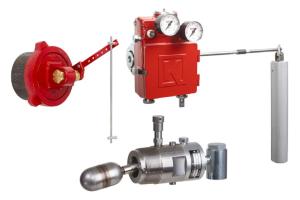
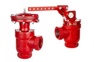
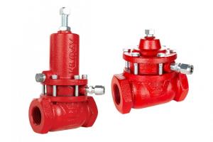
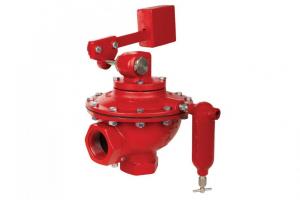

Producers use a Lever-Operated Liquid Dump Valve, Trunnion Assembly and Float to control liquid level in a separator.
Our easy-to-use Dump Valve Torque Calculator (Download) will help you determine what size controller, float, and valve you need for your specific conditions.
Note that there are two tabs—one for two-phase operation and one for three-phase operation.
Here's how it works for two different scenarios:
Scenario 1: size for a 2-phase separator
You have a 2-phase oil vessel (SG=0.7), and you want to determine what size float and length of rod you will need for the trunnion assembly.
- Select the “2-phase inputs” tab.
Determine Specific Weight of the liquid by using the info and formula in Table 1 to calculate, and enter it into Condition 1 column.- Oil, SG 0.7 x 62.22 = 43.554 Note: always multiply by the specific weight of WATER from Table 1, regardless of whether you’re calculating for oil or water.
- Oil, SG 0.7 x 62.22 = 43.554 Note: always multiply by the specific weight of WATER from Table 1, regardless of whether you’re calculating for oil or water.
- Select a float from Table 2 and enter the corresponding info into the blue fields in Condition 1.
If you don’t have any idea where to begin, start with a 7” x 12” Obround float.
- Select any rod length in Table 3 and enter the corresponding info into the green fields in Condition 1.
- Reference the diagram at the bottom to enter the data into the yellow fields in Condition 1.
These entries will depend on the location of the valve relative to the trunnion.
- See “Calculated Torque” results and compare to the data in Table 4.
Calculated Torque must be higher than the Required Torque in Table 4. If they are not, try using one or more of the tips at the bottom.
Tip: You can copy your data from Condition 1 to the other 3 Conditions, then make small changes and compare the different Torque results at the bottom of the calculator page.
Scenario 2: size for interface
You are designing a system to interface between oil (SG 0.8) and water (SG 1.1) at 80F and you already have a Kimray 7” x 16” Float and 12” Rod.
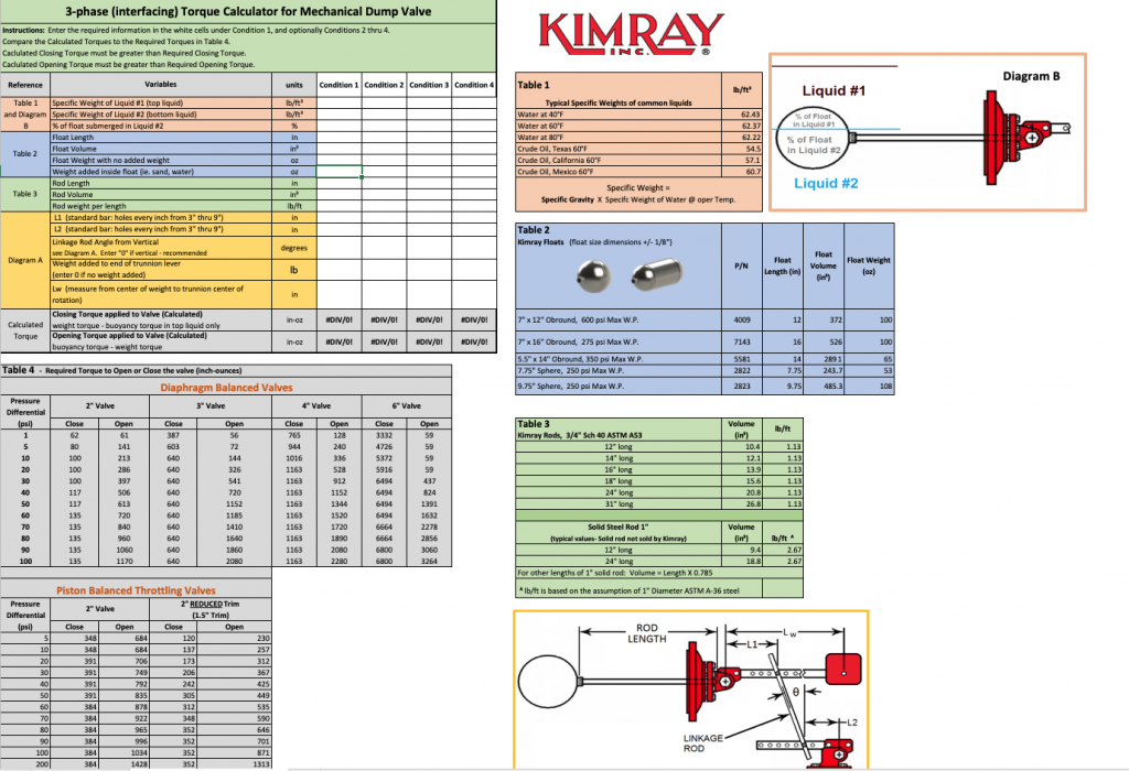
- Select the “3-phase (interfacing) inputs” tab.
Determine Specific Weight of both liquids. Use the info and formula in Table 1 to calculate, and enter these into Condition 1 column.- Oil, SG 0.8 x 62.22 = 49.776 Note: always multiply by the specific weight of WATER from Table 1, regardless of whether you’re calculating for oil or water.
- Water, SG 1.1 x 62.22 = 68.442
- If you want the valve to actuate when the water level is 50% of the way up the float, enter 50 in the Condition 1 column for “% of float submerged in Liquid #2”
- Reference the data in Table 2 and to enter the blue fields into Condition 1 column.
When interfacing you will need to add weight inside the float, typically sand. If you don’t know how much you will use, start with 150 oz in that field and you can adjust later if needed.
- Reference Table 3 to enter Rod data into Condition 1.
- Reference the diagram at the bottom to enter the data into the yellow fields in Condition 1.
These entries will depend on the location of the valve relative to the trunnion. Weight added to trunnion lever is 0 in this example scenario.
- See “Calculated Torque” results and compare to the data in Table 4.
Calculated Torque must be higher than the Required Torque in Table 4. If they are not, try using one or more of the tips at the bottom.
Tip: You can copy your data from Condition 1 to the other 3 Conditions, then make small changes and compare the different Torque results at the bottom of the calculator page.
Download the Torque CalculatorBack to Sizing Calculators
