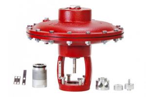
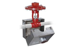
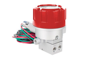
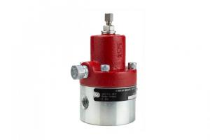
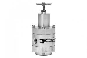
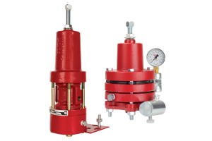
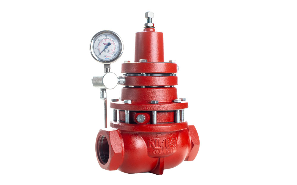
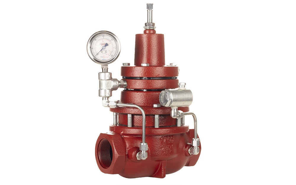
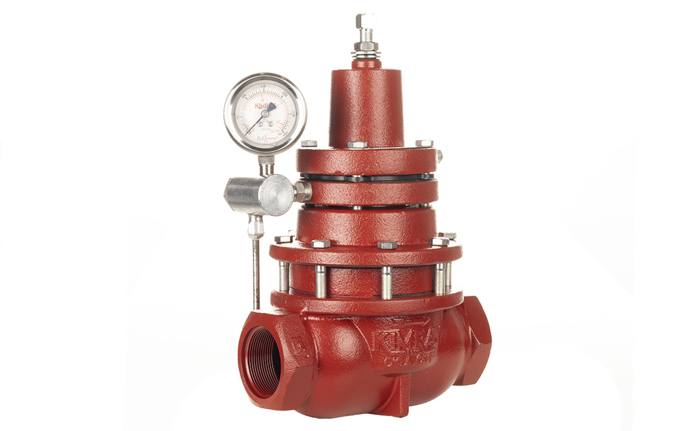
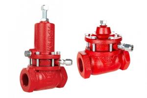
A pressure pilot is used to monitor and control upstream or downstream pressure between 75 and 2500 PSI. It does this by pneumatically positioning a control valve to achieve your desired set point.
The Kimray Bellows Controlled Pressure Pilot is modular, versatile, and easy-to-use in several applications. Part of its value is that it can act in either direct or indirect mode with simple modifications.

In this video, we are going to cover two scenarios:
- Changing the bellows for a different operating pressure
- Converting from indirect to direct acting for repurposing from back pressure to pressure reducing operation
SCENARIO 1: changing the bellows for a different operating pressure
In the bellows controlled pressure pilot, the bellows itself can be changed to better suit your operating conditions. This could be useful if you were previously using a 250 pilot and now needed to control pressures below 200 PSI. For this scenario, we’re going to convert a 250 Pilot to a 75 Pilot which will then operate from 75 to 750 PSI.


The same process can be used to convert a 75 pilot to a 250 pilot, but you will also need to have a (6522) spring ready to install.
Before performing any service, make sure the valve is isolated from all gas sources and that the valve package operating and instrument gas lines are completely depressurized. Never loosen any fittings or valve connections while there is pressure in the lines.

- To begin, make a mark on the pilot so that aligning the components will be easier later during assembly.
- Next, remove the adjustment bolt. The goal is to remove spring tension. You can either take it all the way out or back it out to the point where you can start unthreading it by hand.
- With the valve package isolated from all gas sources, disconnect the tubing.
- Using a 9/16” and 11/16” wrench, remove the bracket bolts to separate the pilot and bracket from the high pressure control valve package.
- Turn the pilot upside down and secure it in a vise.
- Use a 9/16” wrench to remove the four screws from the body.
- Separate the lower housing and the pilot and set them aside.
- Remove the diaphragm plate from the bonnet. If it’s stuck, use a flat-headed screwdriver to remove it.
- Remove the spring plate and inner spring from the bonnet.
- Replace the spring plate and add grease if necessary.
- Replace the diaphragm plate and the pilot, using your markings to make sure it’s aligned.
- To replace the bellows assembly, first remove the lower housing from the main body.
- Unthread and remove the bellows. If it doesn’t come off easily, use a rag for a better grip. If necessary, use channel locks, but be careful not to damage the assembly.
- Carefully remove the (265) O-ring on the bellows. This will need to be reused on the new assembly, so be careful not to damage it.
- It’s also a good idea to inspect the O-ring on the main body. If there is damage, the RBQ repair kit will include replacements for all soft goods.
- Roll the O-ring over the threads to install it on new bellows assembly (5148).
- Thread the new bellows into the lower housing by hand.
- Then reinstall the housing on the main body, pushing down with your hand, and make sure to align the markings.
- Using your markings, align the bonnet, pilot, housing and body. The inlets and outlets will be 90 degrees from the vent port.
- Replace the screws and bracket and tighten with a crisscross pattern, evenly distributing pressure as you tighten.
- In this scenario the pressure range is now between 75 to 750 PSI. The original gauge will work for this pressure range but may be difficult to view accurately. You may want to purchase the appropriate (7708) pressure gauge instead. If you were converting this from a 75 to a 250 Pilot, you would need to purchase a (7710) 2500 PSIG gauge in order to operate it.
- Reattach the pilot to the control valve and install your tubing.

SCENARIO 2: converting from indirect to direct acting
Another way that the pressure pilot is modular is that it can be configured for indirect or direct acting actuation.

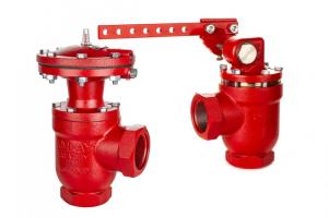
The standard set up for a back pressure valve’s fail position is fail open, which would mean the pilot would be indirect acting.
- With indirect mode, an increase in sense pressure will decrease output pressure to the valve, while a decrease in sense pressure will increase output to the valve.
- With direct-acting mode, an increase in sense pressure will increase output pressure to the valve, while a decrease in sense pressure will decrease output to the valve.
Begin the same way previously shown for changing the bellows assembly:
- To begin, make a mark on the pilot so that during assembling the components will be easier to correctly align.
- With the level controller isolated from all gas sources, disconnect the tubing.
- Using a 9/16” and 11/16”, remove the bracket bolts to separate the pilot and bracket from the high pressure control valve package.
- Next, remove the adjustment bolt. The goal is to remove spring tension. You can either take it all the way out or back it out to the point where you can start unthreading it with your hand.
- Turn the pilot upside down and secure it in a vise.
- Use a 9/16” wrench to remove the four screws from the body.
- Separate the lower housing and main body from the pilot.
- Separate the pilot from the bonnet and set aside.
- Remove both diaphragm plates. If they are stuck, use a flat-headed screwdriver to remove them.
- The two diaphragm plates have different inner diameters. To differentiate between them, look at the grooves on the diaphragms. The width of the diaphragm grooves will match the width of the plate grooves.

- Replace the diaphragm plates on the correct diaphragms.
- Holding the pilot and plates in place, FLIP the unit 180 degrees and place it back on the bonnet.
- In this instance we are only changing the action of the pilot, so this is as much as required for disassembly.
- Using your markings, align the bonnet, pilot, housing and body. Align the sense holes with the supply and output holes. The inlets and outlets will be 90 degrees from the vent port.
- Replace the screws and bracket and tighten with a crisscross pattern, evenly distributing pressure as you tighten.
- At this point, the pilot is ready to be attached to the control valve. However, if the pilot action is changing, the valve fail position will also need to be changed. This will affect the tubing connections for the pilot output and pilot sense line. For more details about building packages for back pressure or pressure reducing applications, watch our other videos for step-by-step instructions.
- When all the components are configured correctly to work together, put the adjustment screw back into the pressure pilot and adjust it accordingly.
To speak with an expert about this conversion, contact your local store or authorized distributor.