What is a Natural Gas Compressor Station?
The natural gas compressor station plays a vital role in the oil and gas industry. Companies construct these stations along natural gas pipelines and use them to compress gas so it can continue flowing downstream to its final destination, which may be a processing facility, a storage tank, or retail or utility companies.
There are a few key components that comprise a typical station:
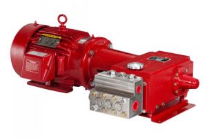
- Compressor. A compressor is a large engine that uses positive displacement to compress gas. A compressor station may have one or multiple compressors on site. Of course, this depends on pipeline needs.
- Scrubbers and filters. Compressor stations also use scrubbers and filters to knock out water, impurities, and hydrocarbons.
- Gas cooling systems. Compressing natural gas causes its temperature to rise. Midstream companies often run the gas through gas cooling systems that lower the gas temperature in order to prevent pipeline damage.
Where are Natural Gas Compressor Stations?
Natural Gas Compressor Stations can be found in numerous places across the United States.
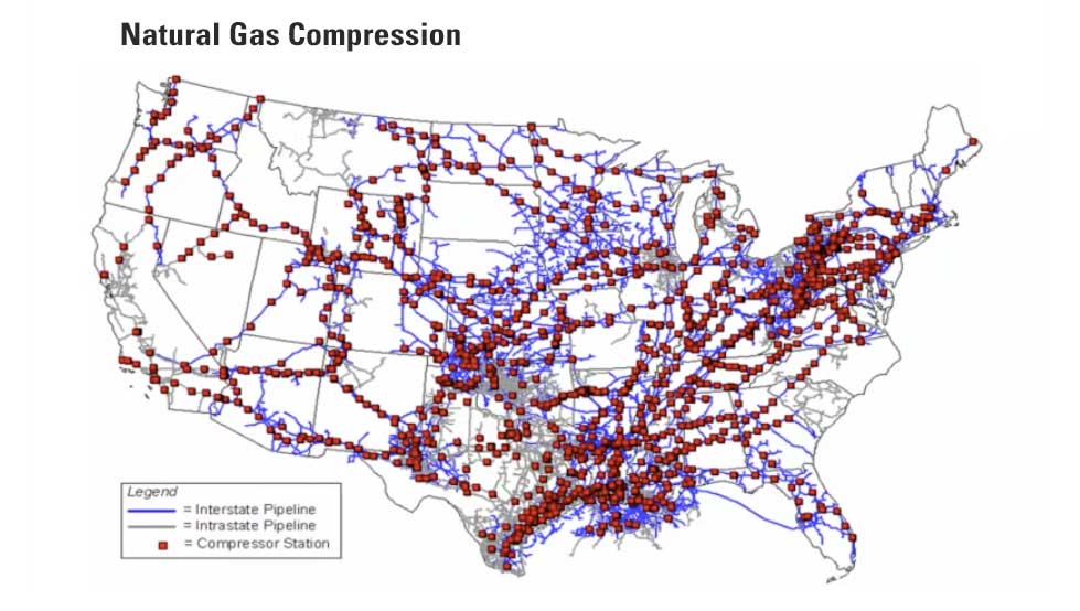
In this natural gas compressor station map, the blue lines are interstate pipelines. Like an interstate highway, these go across states.
The gray lines are intrastate, meaning they serve local regions.
Each red square represents a compressor station. They are located approximately every 40-100 miles depending on the factors like volume, pipeline diameter, terrain and destination.
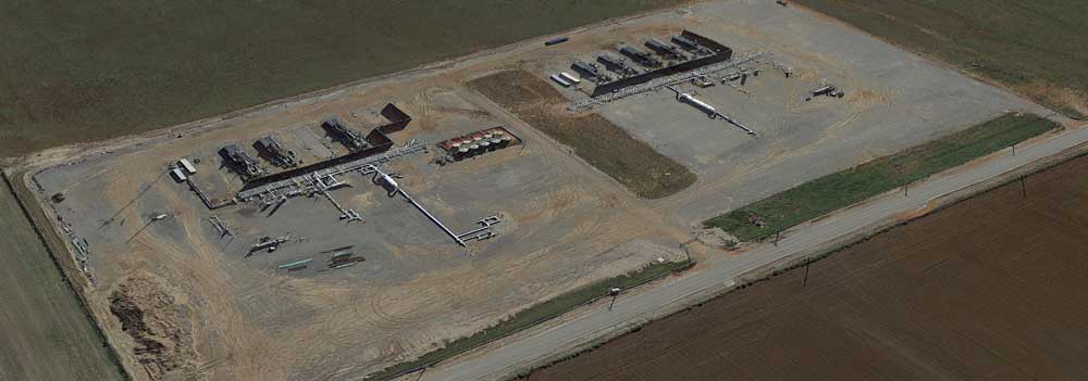
Gas Compressor Station Layout
Below we'll walk through a typical natural gas compression station layout and explain how each piece of equipment works.
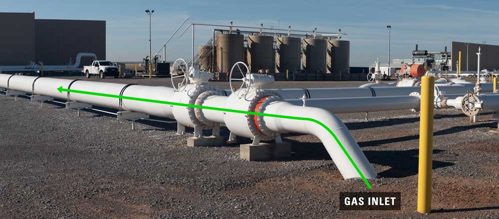
MAIN INLET
The inlet pipe on a compressor station comes from underground and carries natural gas from many different sites. On the video, over 500 well sites are flowing into this station with a flow volume over 45 MMCFD.
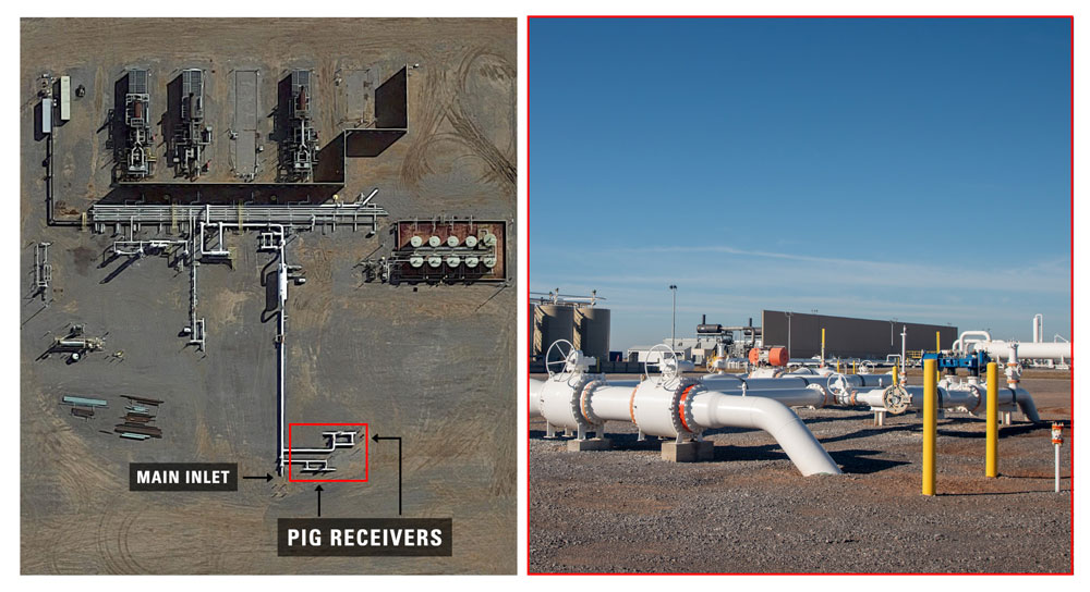
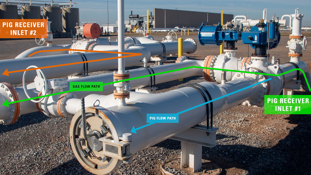
PIG RECEIVER
Also leading into the main inlet on this site are two pig receivers from two different lines. All the process fluid that the pig is pushing through from the pig launcher moves into the main inlet pipeline with the natural gas.
On the pig receiver, the pig trap closure is where an operator would remove pig from the line. The PIG-SIG will indicate that a pig has arrived.
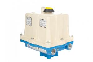
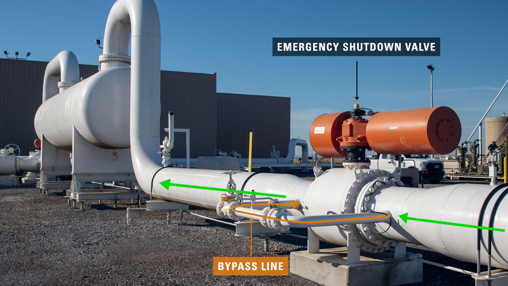
Emergency Shutdown valve (ESD)
Next on the pipeline is an emergency shutdown valve, or ESD. If someone were to press an ESD button, or if the system were over pressure, this will shut-in the system.
In the event of an ESD closure, the bypass line will be used to slowly increase the pressure to resume operation, so the system is not pressurized too quickly during startup.
During regular operation, natural gas is coming into the station at 40-45 PSI. When leaving the station, the final pressure will be between 1250-1300 PSI.
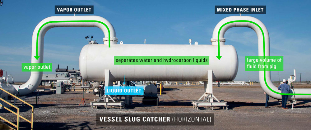
SLUG CATCHER
The slug catcher is designed to handle the large volume of fluid that the pig pushes into the station. It also helps to separate water and hydrocarbon liquids that may condense out of the gas stream as the gas cools and moves through the pipeline.
The large amounts of hydrocarbon liquids and water that the pig pushes into the slug catcher travels to storage tanks on the location in the video.
At this point, a site may use an emulsion breaker to aid this separation process of resources.
After the slug catcher, you may notice more pipes with empty end connections. The station in the video is built to be modular and allow for other equipment to be added in the future if the producer decided it was necessary for increased capacity.
After much of the initial fluids have been removed, the natural gas moves into a second vessel – a filter separator.
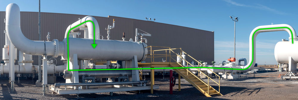
FILTER SEPARATOR
A filter separator removes impurities such as pipe scale, water, iron sulfide, liquid hydrocarbons, compressor lube oil and sulfur products from natural gas.
A filter separator differs from a standard separator vessel in that it uses filter elements to remove contaminants rather than using mechanical devices and other principles of separation. For more on filter separator operation, watch our filter separator video.
This filter separator has a liquid boot design where the liquids fall into the lower portion of the vessel. This is a 2-stage separator, not to be confused with a 2-phase separator. In the first stage liquids fallout and their levels are controlled by this level controller.
In the second stage when the gas passes through the filters, the liquids drop on the other side of the boot and are controlled by a second level controller.
The gas then flows into the suction header and into individual inlets for each compressor.
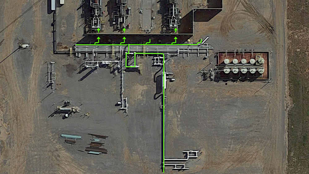
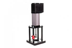
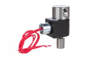
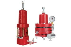
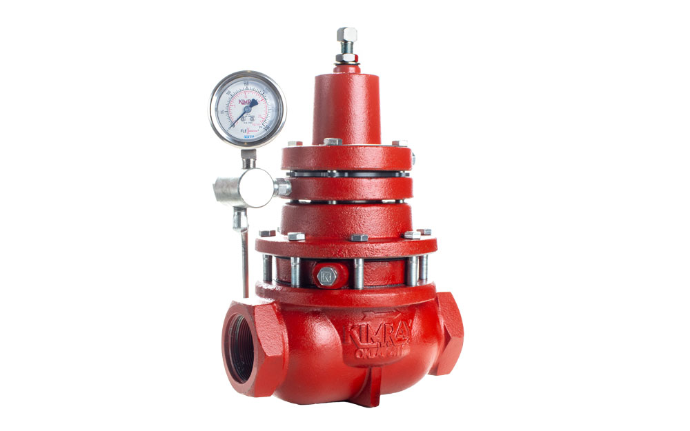
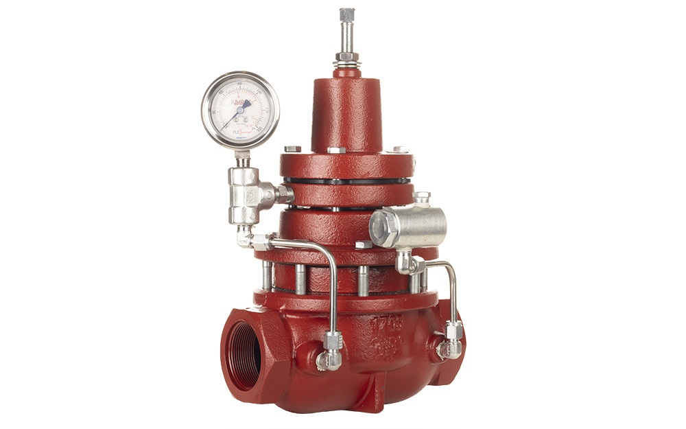
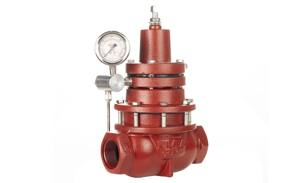
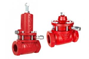
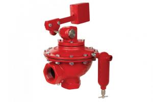
PRESSURE REDUCING PILOT / SUCTION CONTROL VALVE
This pilot is monitoring and controlling the suction of the compressor. The compressor operates most efficiently in a certain window of condition. The suction control valve and pilot prevent the compressor from going down on high or low suction pressure.
After the suction control valve, the natural gas travels through underground pipelines into the inlet scrubber of the compressor that is located on the other side of a sound barrier wall.
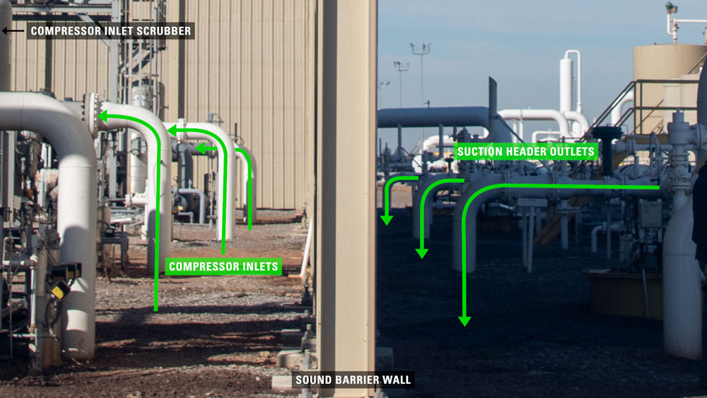
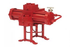
COMPRESSORS
Large compressors like the one in the video are found at compressor stations where high volumes of gas are being gathered from multiple wells over a large area or from a large pipeline. These stations help move gas from one side of the country to the other.
The size and number of compressors found at these stations vary based on the pressures, volume of gas to be moved and the distance it must travel to the next station.
Watch Compressor Function & Flow Video
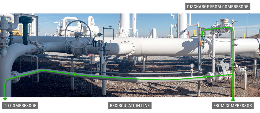
DISCHARGE LINE
After the natural gas has been compressed, the higher pressure allows it to be discharged into a smaller pipeline at the same flow rate.
Also coming off the main discharge line is a recirculation line. This can be used if the gas needs to run back through the compressor again.
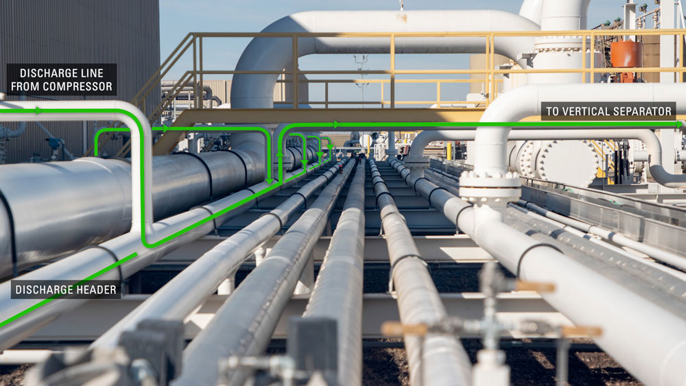
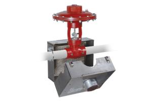
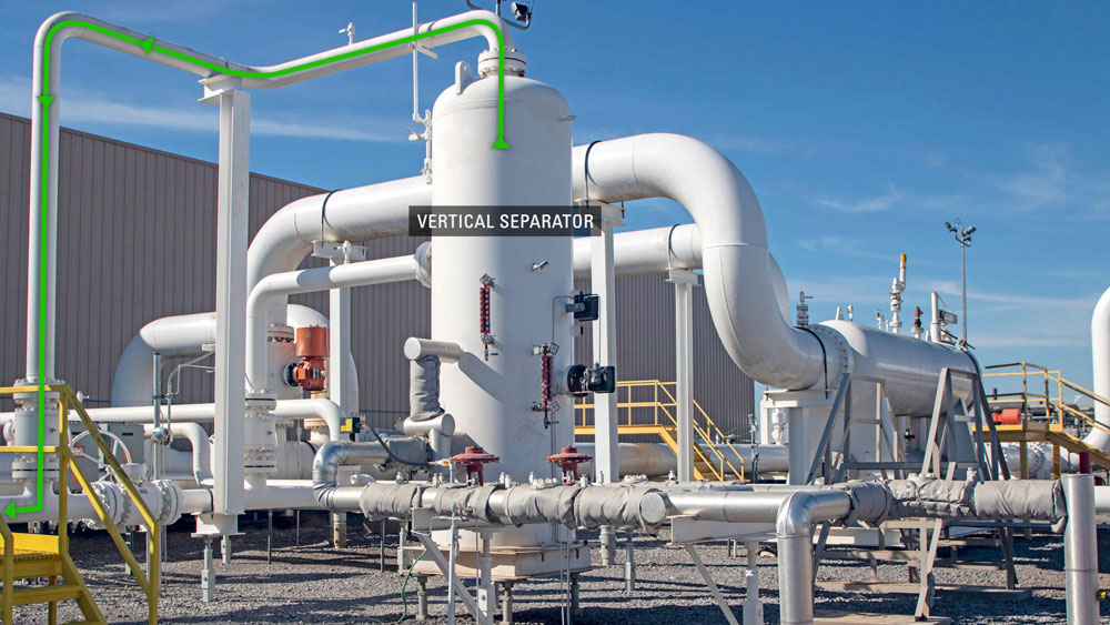
VERTICAL SEPARATOR
The discharge line from each compressor travels into the discharge header which then enters a vertical separator. After the natural gas has been compressed and then cooled, more condensation will be present in the gas stream. This vertical separator is removing those condensed liquids from the gas.
FILTER SEPARATOR
Another filter separator is used to remove more impurities such as pipe scale, water, iron sulfide, liquid hydrocarbons, compressor lube oil and sulfur products from natural gas.
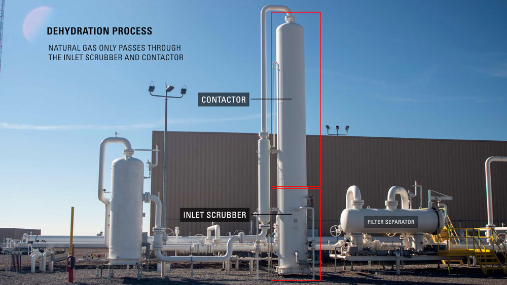
DEHYDRATION
There is a lot of equipment needed for the dehydration process.
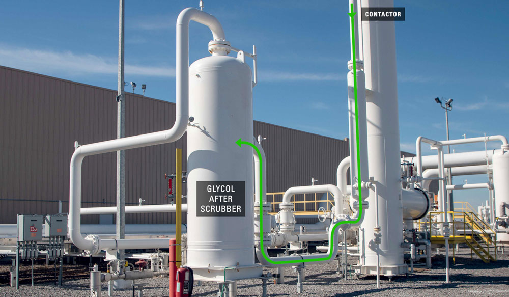
Natural gas only travels through the inlet scrubber and the contactor. On the site in the video, these two vessels are combined into one unit. All the other equipment is used to regenerate the glycol used in the dehydration process and is located slightly farther away, connected by underground pipelines.
Watch Natural Gas Dehydration Video
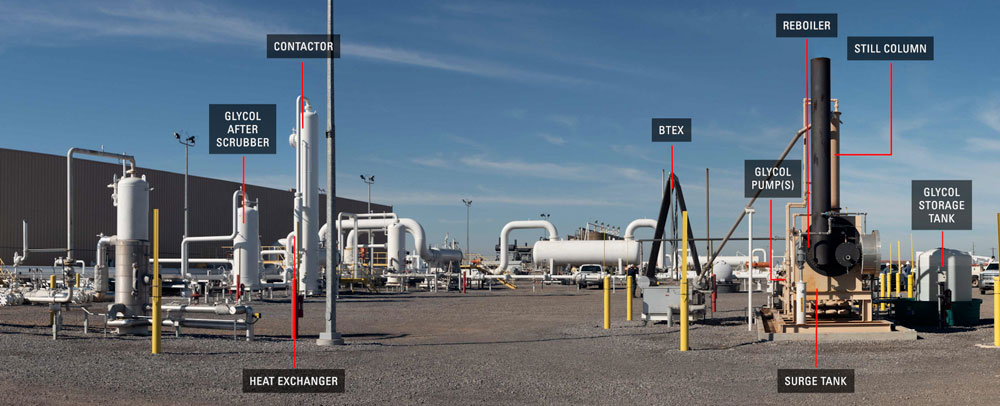
GLYCOL AFTER SCRUBBER
The next vessel is a Glycol After Scrubber. The function is to capture any glycol that the gas sweeps out of the tower due to foaming. This could be caused by high Ph levels or a high temperature differential between the gas and glycol.
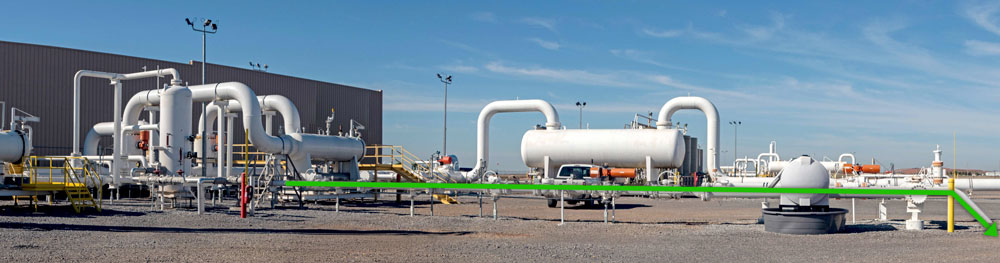
OUTLET
When the natural gas exits the glycol after scrubber, it moves back into discharge pipeline and travels underground to the next compressor station or destination.
GAS FLARE
The gas flare is used to destroy excess gas during startup or shutdown processes and when pressure needs to be relieved from equipment.
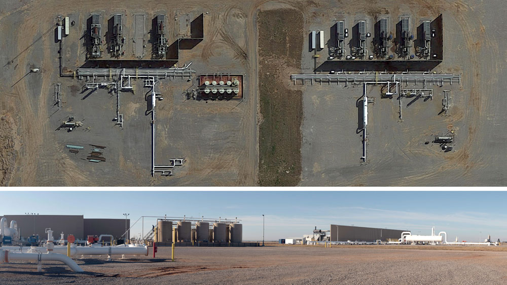
DUAL COMPRESSION SITE
This site was expanded to handle an increased production from additional wells. The new higher volume was great enough to require additional equipment, rather than replacing it with larger vessels. This also allows for even more increase in production in the future.
This additional equipment is an almost identical setup to what was just discussed with some exceptions like a larger slug catcher and the number of compressors.
The purpose of these vessels and components is to take the raw natural gas from many sources, clean and pressurize the gas and send it miles away to the next station or gas processing plant.
To speak with an expert about your compressor control, contact your local Kimray store or authorized distributor.